Section 1
SAFETY
8
E.
Check fluid level. If low, bring fluid to proper level
before attempting to jump start (not applicable to
maintenance-free batteries).
F. DO NOT
attempt to jump start if fluid is frozen or
slushy. Bring batteries up to at least 60°F (16°C)
before attempting to jump start or it may explode.
G.
Cover open cells of all compressor batteries with
clean dampened cloths before attempting to jump
start.
H.
Attempt to jump start only with a vehicle having
a negative ground electrical system with the same
voltage, and is also equipped with a battery or bat-
teries of comparable size or larger than supplied in
the compressor.
DO NOT
attempt to jump start
using motor generator sets, welders or other
sources of DC power as serious damage may
result.
I.
Bring the starting vehicle alongside the compres-
sor, but
DO NOT
permit metal to metal contact
between the compressor and the starting vehicle.
J.
Set the parking brakes of both the compressor (if
provided) and the starting vehicle or otherwise
block both sides of all wheels.
K.
Place the starting vehicle in neutral or park, turn
off all non-essential accessory electrical loads and
start its engine.
L.
Use only jumper cables that are clean, in good
condition and are heavy enough to handle the start-
ing current.
M.
Avoid accidental contact between jumper cable
terminal clips or clamps and any metallic portion of
either the compressor or the starting vehicle to min-
imize the possibility of uncontrolled arcing which
might serve as a source of ignition.
N.
Positive battery terminals are usually identified
by a plus (+) sign on the terminal and the letters
POS adjacent to the terminal. Negative battery ter-
minals are usually identified by the letters NEG
adjacent to the terminal or a negative (-) sign.
O.
Connect one end of a jumper cable to the posi-
tive (POS) (+) battery terminal in the starting vehi-
cle. When jump starting 24V compressors and if the
starting vehicle is provided with two (2) 12V batter-
ies connected in series, connect the jumper cable
to the positive (POS) (+) terminal of the unground-
ed battery.
P.
Connect the other end of the same jumper cable
to the positive (POS) (+) terminal of the starter
motor battery in the compressor, or when jump
starting 24V compressor, to the positive (POS) (+)
terminal of the ungrounded battery in the compres-
sor.
Q.
Connect one end of the other jumper cable to
the grounded negative (NEG) (-) terminal of the bat-
tery in the starting vehicle. When jump starting 24V
compressors and if the starting vehicle is provided
with two (2) 12V batteries connected in series, con-
nect the jumper cable to the negative (NEG) (-) ter-
minal of the grounded battery.
R.
Check your connections.
DO NOT
attempt to
start a 24V compressor with one 12V battery in the
starting vehicle.
DO NOT
apply 24V to one 12V
battery in the compressor.
S.
Connect the other end of this same jumper cable
to a clean portion of the compressor engine block
away from fuel lines, the crank case breather open-
ing and the battery.
T.
Start the compressor in accordance with normal
procedure. Avoid prolonged cranking.
U.
Allow the compressor to warm up. When the
compressor is warm and operating smoothly at nor-
mal idle RPM, disconnect the jumper cable from the
engine block in the compressor, then disconnect
the other end of this same cable from the grounded
negative (NEG) (-) terminal of the battery in the
starting vehicle. Then disconnect the other jumper
cable from the positive (POS) (+) terminal of the
battery in the compressor, or if provided with two (2)
12V batteries connected in series, from the
ungrounded battery in the compressor, and finally,
disconnect the other end of this same jumper cable
from the positive (POS) (+) terminal of the battery in
the starting vehicle or from the positive (POS) (+)
terminal of the ungrounded battery in the starting
vehicle, if it is provided with two (2) 12V batteries
connected in series.
V.
Remove and carefully dispose of the dampened
cloths, as they may now be contaminated with acid,
then replace all vent caps.
Summary of Contents for 1350XH
Page 6: ......
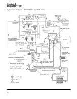
Page 18: ...Section 2 DESCRIPTION 12 Figure 2 3A Control System 900XH 1150XH and 1350XH Models...
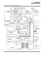
Page 19: ...Section 2 DESCRIPTION 13 Figure 2 3B Control System Aftercooled Models...
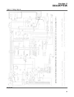
Page 29: ...Section 2 DESCRIPTION 23 Figure 2 7 Wiring Diagram 02250145 161R01...
Page 30: ...NOTES 24...
Page 33: ...Section 3 SPECIFICATIONS 27 02250135 977R03 Figure 3 2 Identification Compressor Assembly...
Page 34: ...NOTES 28...
Page 38: ...NOTES 32...
Page 54: ...Section 7 ILLUSTRATIONS AND PARTS 48 02250127 622R08 7 3 ENGINE AND COMPRESSOR MOUNTING...
Page 56: ...Section 7 ILLUSTRATIONS AND PARTS 50 02250127 622R08 7 3 ENGINE AND COMPRESSOR MOUNTING...
Page 58: ...Section 7 ILLUSTRATIONS AND PARTS 52 02250136 060R02 7 4 AIR INLET SYSTEM ALL MODELS...
Page 60: ...Section 7 ILLUSTRATIONS AND PARTS 54 02250136 060R02 7 4 AIR INLET SYSTEM ALL MODELS...
Page 62: ...Section 7 ILLUSTRATIONS AND PARTS 56 02250136 062R02 7 5 EXHAUST SYSTEM ALL MODELS...
Page 72: ...Section 7 ILLUSTRATIONS AND PARTS 66 02250127 633R02 7 7 ENGINE RADIATOR ASSEMBLY ALL MODELS...
Page 74: ...Section 7 ILLUSTRATIONS AND PARTS 68 7 8 AFTERCOOLER MOUNTING ALL MODELS 02250150 135R03...
Page 82: ...Section 7 ILLUSTRATIONS AND PARTS 76 02250140 983R01 7 12A INLET VALVE AND PARTS 6 5 900XH...
Page 86: ...Section 7 ILLUSTRATIONS AND PARTS 80 02250054 762R06 7 13A INLET VALVE PARTS 6 5 900XH...
Page 90: ...Section 7 ILLUSTRATIONS AND PARTS 84 02250127 667R10 7 14A DISCHARGE SYSTEM 900XH AND 1150XH...
Page 96: ...Section 7 ILLUSTRATIONS AND PARTS 90 02250148 288R01 7 14C DISCHARGE SYSTEM 1350XH AFTERCOOLED...
Page 98: ...Section 7 ILLUSTRATIONS AND PARTS 92 02250148 288R01 7 14C DISCHARGE SYSTEM 1350XH AFTERCOOLED...
Page 116: ...Section 7 ILLUSTRATIONS AND PARTS 110 02250164 870R01 7 19 MINIMUM PRESSURE CHECK VALVE...
Page 118: ...Section 7 ILLUSTRATIONS AND PARTS 112 02250136 066R00 7 20 FUEL SYSTEM AND PARTS ALL MODELS...
Page 120: ...Section 7 ILLUSTRATIONS AND PARTS 114 02250127 727R01 7 21 ELECTRICAL PARTS ALL MODELS...
Page 126: ...Section 7 ILLUSTRATIONS AND PARTS 120 02250136 503R02 7 23 FRAME AND PARTS...
Page 128: ...Section 7 ILLUSTRATIONS AND PARTS 122 7 24 DECAL GROUP...
Page 130: ...Section 7 ILLUSTRATIONS AND PARTS 124 7 24 DECAL GROUP...
Page 132: ...Section 7 ILLUSTRATIONS AND PARTS 126 7 24 DECAL GROUP...
Page 134: ...Section 7 ILLUSTRATIONS AND PARTS 128 7 24 DECAL GROUP...
Page 136: ...Section 7 ILLUSTRATIONS AND PARTS 130 7 25 DECAL LOCATIONS 02250136 067R03...
Page 138: ...Section 7 ILLUSTRATIONS AND PARTS 132 7 25 DECAL LOCATIONS 02250136 067R03...
Page 140: ...NOTES 134...
Page 141: ......


