Section 3
SPECIFICATIONS
26
3.2 LUBRICATION GUIDE - COMPRESSOR
FLUID TYPE
CHANGE PERIOD, HOURS
AMBIENT TEMPERATURE RANGE °F (°C)
Sullair AWF
(I)
500
-20 to 120 (-29 to 49)
Mobil Rarus SHC 1026
800
50 to 125 (10 to 52)
Mobil Rarus SHC 1024
1000
-20 to 100 (-29 to 38)
(I)
Sullair part numbers for multi-viscosity lubricants are 250030-757 for 5 gallon / 20 liter container, and
250030-758 for 55 gallon / 208 liter container.
3.3 APPLICATION GUIDE
. Sullair Air Compressors are
supplied with Sullair AWF which is heavy duty multi-
viscosity, all-weather fluid. Sullair AWF also allows
an extended change interval. Detergent motor oils
(SAE 10W Class SE, SF, SG or CD) can also be
used. Any of these oils are suitable under condi-
tions where severe oil oxidations can occur.
Water must be drained from the receiver periodical-
ly. In high ambient temperature and high humidity
conditions, condensed moisture may emulsify with
the oil forming a “milky” color. SAE 10W is espe-
cially prone to this condition. The fluid should be
changed if this condition develops.
When ambient conditions exceed those noted or if
conditions warrant use of other extended life lubri-
cants, contact Sullair for recommendations.
Sullair encourages the user to participate in a fluid
analysis program. This could result in a fluid change
interval differing from that stated in the manual.
Sullair Corporation offers a fluid analysis program
for Sullair AWF. Contact your local Sullair represen-
tative for details.
D-A Lubricant® Company Inc. offers an analysis
program for users of D-A products and Sullair AWF.
Contact your D-A lubricant supplier or Sullair repre-
sentative for details.
3.4 LUBRICATION GUIDE - ENGINE
For engine oil specifications, refer to the Engine
Operator’s Manual.
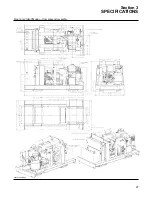
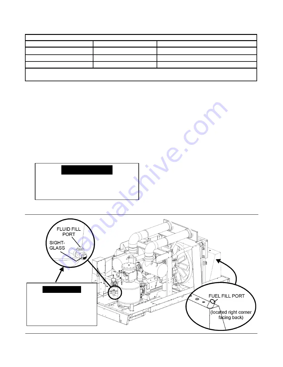
Figure 3-1 Fluid and Fuel Fill Port Locations - Typical Locations
When performing a fluid
change or topping off the
fill, the proper level should
be at half of the sight glass,
with the machine off.
NOTE
DO NOT
mix types of fluids.
Combinations of different fluids may lead
to operational problems such as foaming,
filter plugging, orifice or line plugging.
CAUTION
Summary of Contents for 1350XH
Page 6: ......
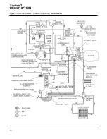
Page 18: ...Section 2 DESCRIPTION 12 Figure 2 3A Control System 900XH 1150XH and 1350XH Models...
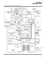
Page 19: ...Section 2 DESCRIPTION 13 Figure 2 3B Control System Aftercooled Models...
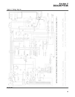
Page 29: ...Section 2 DESCRIPTION 23 Figure 2 7 Wiring Diagram 02250145 161R01...
Page 30: ...NOTES 24...
Page 33: ...Section 3 SPECIFICATIONS 27 02250135 977R03 Figure 3 2 Identification Compressor Assembly...
Page 34: ...NOTES 28...
Page 38: ...NOTES 32...
Page 54: ...Section 7 ILLUSTRATIONS AND PARTS 48 02250127 622R08 7 3 ENGINE AND COMPRESSOR MOUNTING...
Page 56: ...Section 7 ILLUSTRATIONS AND PARTS 50 02250127 622R08 7 3 ENGINE AND COMPRESSOR MOUNTING...
Page 58: ...Section 7 ILLUSTRATIONS AND PARTS 52 02250136 060R02 7 4 AIR INLET SYSTEM ALL MODELS...
Page 60: ...Section 7 ILLUSTRATIONS AND PARTS 54 02250136 060R02 7 4 AIR INLET SYSTEM ALL MODELS...
Page 62: ...Section 7 ILLUSTRATIONS AND PARTS 56 02250136 062R02 7 5 EXHAUST SYSTEM ALL MODELS...
Page 72: ...Section 7 ILLUSTRATIONS AND PARTS 66 02250127 633R02 7 7 ENGINE RADIATOR ASSEMBLY ALL MODELS...
Page 74: ...Section 7 ILLUSTRATIONS AND PARTS 68 7 8 AFTERCOOLER MOUNTING ALL MODELS 02250150 135R03...
Page 82: ...Section 7 ILLUSTRATIONS AND PARTS 76 02250140 983R01 7 12A INLET VALVE AND PARTS 6 5 900XH...
Page 86: ...Section 7 ILLUSTRATIONS AND PARTS 80 02250054 762R06 7 13A INLET VALVE PARTS 6 5 900XH...
Page 90: ...Section 7 ILLUSTRATIONS AND PARTS 84 02250127 667R10 7 14A DISCHARGE SYSTEM 900XH AND 1150XH...
Page 96: ...Section 7 ILLUSTRATIONS AND PARTS 90 02250148 288R01 7 14C DISCHARGE SYSTEM 1350XH AFTERCOOLED...
Page 98: ...Section 7 ILLUSTRATIONS AND PARTS 92 02250148 288R01 7 14C DISCHARGE SYSTEM 1350XH AFTERCOOLED...
Page 116: ...Section 7 ILLUSTRATIONS AND PARTS 110 02250164 870R01 7 19 MINIMUM PRESSURE CHECK VALVE...
Page 118: ...Section 7 ILLUSTRATIONS AND PARTS 112 02250136 066R00 7 20 FUEL SYSTEM AND PARTS ALL MODELS...
Page 120: ...Section 7 ILLUSTRATIONS AND PARTS 114 02250127 727R01 7 21 ELECTRICAL PARTS ALL MODELS...
Page 126: ...Section 7 ILLUSTRATIONS AND PARTS 120 02250136 503R02 7 23 FRAME AND PARTS...
Page 128: ...Section 7 ILLUSTRATIONS AND PARTS 122 7 24 DECAL GROUP...
Page 130: ...Section 7 ILLUSTRATIONS AND PARTS 124 7 24 DECAL GROUP...
Page 132: ...Section 7 ILLUSTRATIONS AND PARTS 126 7 24 DECAL GROUP...
Page 134: ...Section 7 ILLUSTRATIONS AND PARTS 128 7 24 DECAL GROUP...
Page 136: ...Section 7 ILLUSTRATIONS AND PARTS 130 7 25 DECAL LOCATIONS 02250136 067R03...
Page 138: ...Section 7 ILLUSTRATIONS AND PARTS 132 7 25 DECAL LOCATIONS 02250136 067R03...
Page 140: ...NOTES 134...
Page 141: ......

