Section 5
MAINTENANCE
36
CONTROL SYSTEM ADJUSTMENT
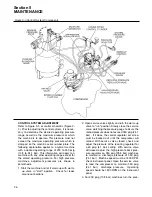
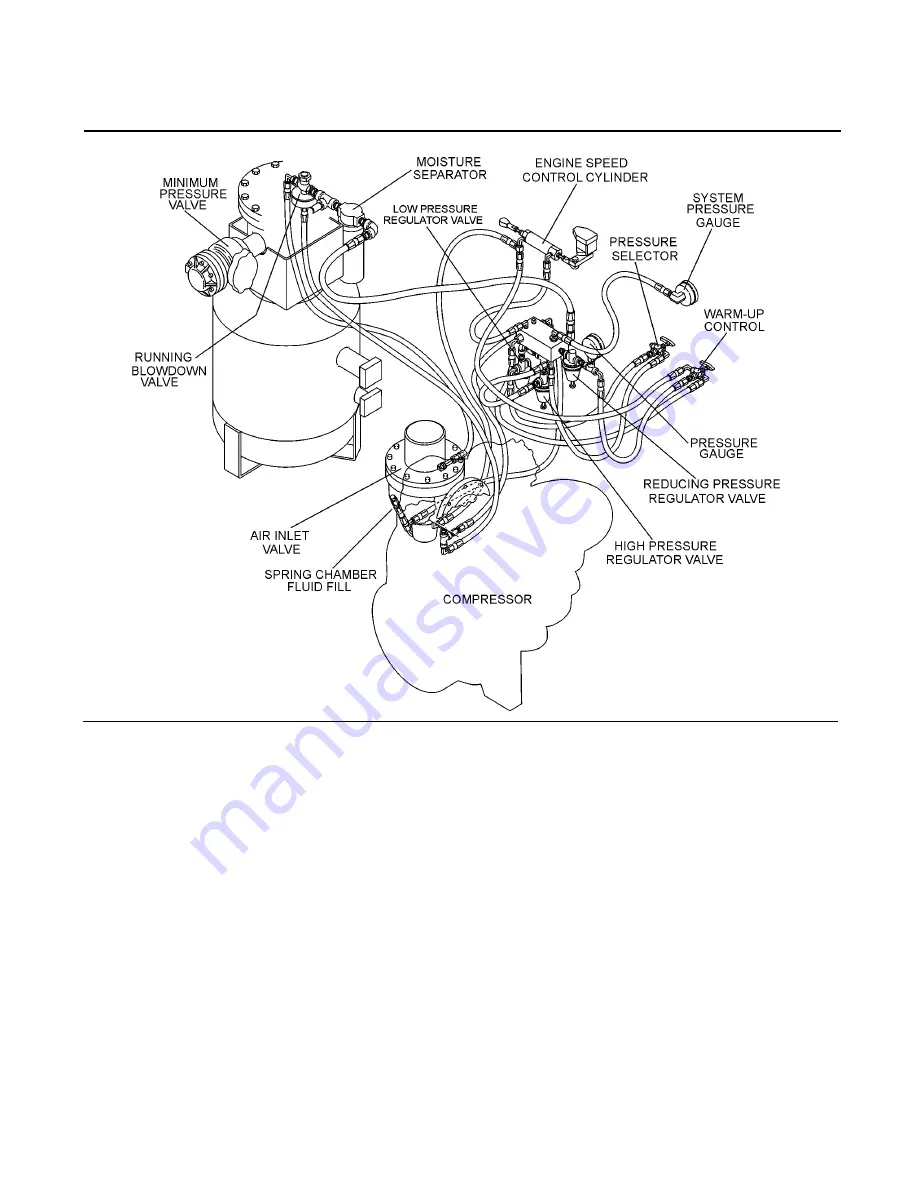
Refer to Figure 5-3, or control schematic (Figure 2-
3). Prior to adjusting the control system, it is neces-
sary to determine the desired operating pressure
range as well as the maximum pressure at which
the machine is to operate. This pressure must not
exceed the maximum operating pressure which is
stamped on the machine serial number plate. The
following explanation applies to a typical machine
with a desired operating range of 200 to 350 psig
(13.8 to 24.1 bar). This information will apply to a
machine with any other operating range except for
the stated operating pressure. For high pressure
machines, adjustment pressures are shown in
parenthesis.
1. Start the machine and let it warm-up with warm-
up valve in "start" position. Check for leaks
around connections.
2. Open service valve slightly and turn the warm-up
valve to "run" position. Slowly close the service
valve, watching the pressure gauge to insure the
unload pressure does not exceed 350 psig (24.1
bar) . If it does, the control regulator set screw
must be backed out until the compressor will
unload. With service valve closed, check and
adjust the pressure at the reducing regulator for
a 60 psig (4.1 bar) setting. With service valve
still closed, adjust the high pressure back pres-
sure regulator on 350 psig [25.5 bar] machines
to maintain a discharge pressure of 350 psig
(24.1 bar) . Machine speed must be 1400 RPM,
check instrument panel. Open the service valve
to load the compressor to maintain 350 psig
(24.1 bar) discharge pressure. Operating
speed should be 1800 RPM on the instrument
panel.
3. For 200 psig (13.8 bar) machines turn the pres-
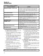
Figure 5-3 Control System Components
Summary of Contents for 1350XH
Page 6: ......
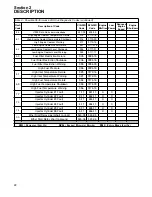
Page 18: ...Section 2 DESCRIPTION 12 Figure 2 3A Control System 900XH 1150XH and 1350XH Models...
Page 19: ...Section 2 DESCRIPTION 13 Figure 2 3B Control System Aftercooled Models...
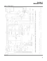
Page 29: ...Section 2 DESCRIPTION 23 Figure 2 7 Wiring Diagram 02250145 161R01...
Page 30: ...NOTES 24...
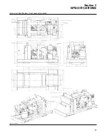
Page 33: ...Section 3 SPECIFICATIONS 27 02250135 977R03 Figure 3 2 Identification Compressor Assembly...
Page 34: ...NOTES 28...
Page 38: ...NOTES 32...
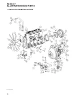
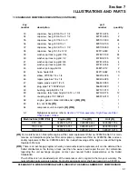
Page 54: ...Section 7 ILLUSTRATIONS AND PARTS 48 02250127 622R08 7 3 ENGINE AND COMPRESSOR MOUNTING...
Page 56: ...Section 7 ILLUSTRATIONS AND PARTS 50 02250127 622R08 7 3 ENGINE AND COMPRESSOR MOUNTING...
Page 58: ...Section 7 ILLUSTRATIONS AND PARTS 52 02250136 060R02 7 4 AIR INLET SYSTEM ALL MODELS...
Page 60: ...Section 7 ILLUSTRATIONS AND PARTS 54 02250136 060R02 7 4 AIR INLET SYSTEM ALL MODELS...
Page 62: ...Section 7 ILLUSTRATIONS AND PARTS 56 02250136 062R02 7 5 EXHAUST SYSTEM ALL MODELS...
Page 72: ...Section 7 ILLUSTRATIONS AND PARTS 66 02250127 633R02 7 7 ENGINE RADIATOR ASSEMBLY ALL MODELS...
Page 74: ...Section 7 ILLUSTRATIONS AND PARTS 68 7 8 AFTERCOOLER MOUNTING ALL MODELS 02250150 135R03...
Page 82: ...Section 7 ILLUSTRATIONS AND PARTS 76 02250140 983R01 7 12A INLET VALVE AND PARTS 6 5 900XH...
Page 86: ...Section 7 ILLUSTRATIONS AND PARTS 80 02250054 762R06 7 13A INLET VALVE PARTS 6 5 900XH...
Page 90: ...Section 7 ILLUSTRATIONS AND PARTS 84 02250127 667R10 7 14A DISCHARGE SYSTEM 900XH AND 1150XH...
Page 96: ...Section 7 ILLUSTRATIONS AND PARTS 90 02250148 288R01 7 14C DISCHARGE SYSTEM 1350XH AFTERCOOLED...
Page 98: ...Section 7 ILLUSTRATIONS AND PARTS 92 02250148 288R01 7 14C DISCHARGE SYSTEM 1350XH AFTERCOOLED...
Page 116: ...Section 7 ILLUSTRATIONS AND PARTS 110 02250164 870R01 7 19 MINIMUM PRESSURE CHECK VALVE...
Page 118: ...Section 7 ILLUSTRATIONS AND PARTS 112 02250136 066R00 7 20 FUEL SYSTEM AND PARTS ALL MODELS...
Page 120: ...Section 7 ILLUSTRATIONS AND PARTS 114 02250127 727R01 7 21 ELECTRICAL PARTS ALL MODELS...
Page 126: ...Section 7 ILLUSTRATIONS AND PARTS 120 02250136 503R02 7 23 FRAME AND PARTS...
Page 128: ...Section 7 ILLUSTRATIONS AND PARTS 122 7 24 DECAL GROUP...
Page 130: ...Section 7 ILLUSTRATIONS AND PARTS 124 7 24 DECAL GROUP...
Page 132: ...Section 7 ILLUSTRATIONS AND PARTS 126 7 24 DECAL GROUP...
Page 134: ...Section 7 ILLUSTRATIONS AND PARTS 128 7 24 DECAL GROUP...
Page 136: ...Section 7 ILLUSTRATIONS AND PARTS 130 7 25 DECAL LOCATIONS 02250136 067R03...
Page 138: ...Section 7 ILLUSTRATIONS AND PARTS 132 7 25 DECAL LOCATIONS 02250136 067R03...
Page 140: ...NOTES 134...
Page 141: ......

