Section 5
MAINTENANCE
37
sure selector valve to "low" position. Close the
service valve and set the low pressure back
pressure regulator to maintain 210 psig (14.5
bar) discharge pressure. Open the service valve
to maintain 200 psig (13.8 bar) and check for
1800 RPM full load speed. If lower speed is
observed, raise the setting of the low pressure
control regulator until rated speed is achieved.
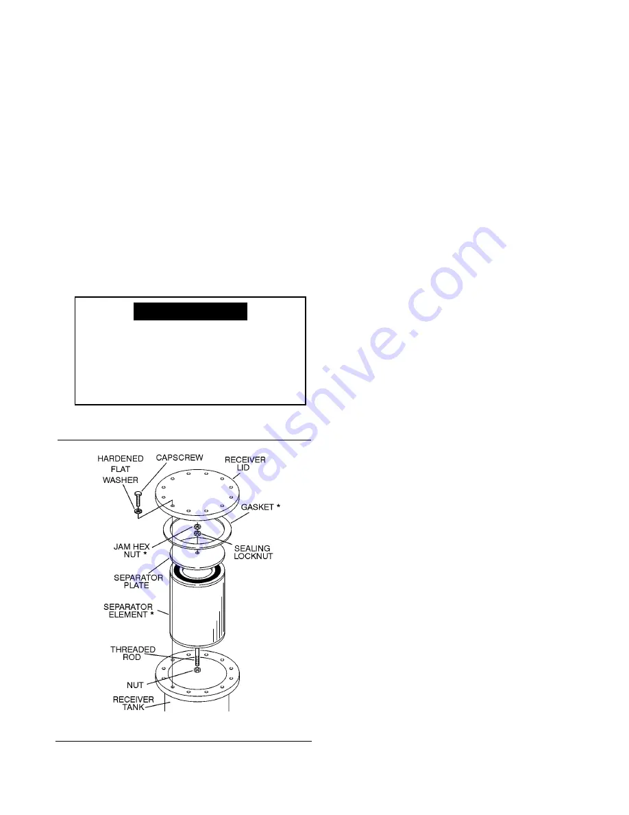
SEPARATOR ELEMENT REPLACEMENT
. When the need for a separator
element replacement is indicated by the mainte-
nance indicator (usually mounted to the air receiv-
er/separator tank but can also be remote mounted),
use the following procedure for separator replace-
ment.
1. Remove the air receiver/separator tank lid by
removing the twelve (12) hex head capscrews.
2. Remove the 3/4"-10 jam nut and sealing hex nut
from the 3/4"-10 separator hold down rod.
3. Remove the round separator cover plate from the
top of the separator element.
4. Remove the old separator element and discard.
5. Scrape the old gasket material from the tank lid
mounting surface and the flanges mounting sur-
face on the tank. Be sure to keep all scrapings
from falling back inside of the tank.
6. Before installing the new separator element,
make sure to lubricate both sealing o-rings on
the element with a lubricating compound (i.e.
Silglyde). Then install the new separator ele-
ment, the cover plate, the new 3/4"-10 sealing
hex nut, and the 3/4"-10 jam hex nut. Torque the
sealing hex nut to 85 to 90 ft.-lbs. (115 to 122
Nm).
DO NOT
over-tighten, as damage to sepa-
rator element can result.
7. Next, install the tank flange gasket that is provid-
ed. Before installing, lubricate both sides of the
gasket (i.e. Silglyde). Reinstall the tank lid.
Install the capscrews finger tight, then gradually
tighten in a crisscross pattern in 4 to 5 steps.
Always tighten the capscrews alternately at
opposite sides of the cover. Torque lubricated
capscrews to 280ft.-lbs. (380 Nm).
8. Clean or replace fluid return line strainer.
9. Clean the fluid return line orifice installed in the
side of the compressor unit air end.
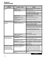
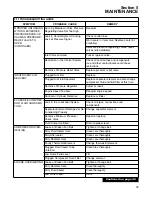
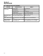
5.10 TROUBLESHOOTING
The following Troubleshooting Chart is based on
both the data obtained from actual tests conducted
at our factory and real applied situations. It contains
symptoms and usual causes for the described prob-
lems. However,
DO NOT
assume that these are the
only problems that may occur. All available data
concerning the trouble should be systematically
analyzed before undertaking any repairs or compo-
nent replacement procedures.
• Check for loose wiring.
• Check for damaged piping.
• Check for parts damaged by heat or an elec-
trical short circuit, usually apparent by dis-
coloration or a burnt odor.
Should your problem persist after making the rec-
ommended check, consult your nearest Sullair rep-
resentative or the Sullair Corporation.
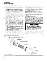
Figure 5-4 Separator Element
To assist with the removal of the tank
lid, Sullair has provided a 1"-8 nut to
the top lid so it can be removed by a 1"-
8 eye bolt (which is available from
Sullair) or a similar type of lifting
device.
NOTE
*Repair Kit P/N 250028-244
Summary of Contents for 1350XH
Page 6: ......
Page 18: ...Section 2 DESCRIPTION 12 Figure 2 3A Control System 900XH 1150XH and 1350XH Models...
Page 19: ...Section 2 DESCRIPTION 13 Figure 2 3B Control System Aftercooled Models...
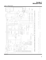
Page 29: ...Section 2 DESCRIPTION 23 Figure 2 7 Wiring Diagram 02250145 161R01...
Page 30: ...NOTES 24...
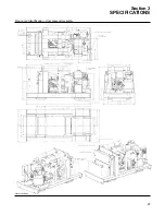
Page 33: ...Section 3 SPECIFICATIONS 27 02250135 977R03 Figure 3 2 Identification Compressor Assembly...
Page 34: ...NOTES 28...
Page 38: ...NOTES 32...
Page 54: ...Section 7 ILLUSTRATIONS AND PARTS 48 02250127 622R08 7 3 ENGINE AND COMPRESSOR MOUNTING...
Page 56: ...Section 7 ILLUSTRATIONS AND PARTS 50 02250127 622R08 7 3 ENGINE AND COMPRESSOR MOUNTING...
Page 58: ...Section 7 ILLUSTRATIONS AND PARTS 52 02250136 060R02 7 4 AIR INLET SYSTEM ALL MODELS...
Page 60: ...Section 7 ILLUSTRATIONS AND PARTS 54 02250136 060R02 7 4 AIR INLET SYSTEM ALL MODELS...
Page 62: ...Section 7 ILLUSTRATIONS AND PARTS 56 02250136 062R02 7 5 EXHAUST SYSTEM ALL MODELS...
Page 72: ...Section 7 ILLUSTRATIONS AND PARTS 66 02250127 633R02 7 7 ENGINE RADIATOR ASSEMBLY ALL MODELS...
Page 74: ...Section 7 ILLUSTRATIONS AND PARTS 68 7 8 AFTERCOOLER MOUNTING ALL MODELS 02250150 135R03...
Page 82: ...Section 7 ILLUSTRATIONS AND PARTS 76 02250140 983R01 7 12A INLET VALVE AND PARTS 6 5 900XH...
Page 86: ...Section 7 ILLUSTRATIONS AND PARTS 80 02250054 762R06 7 13A INLET VALVE PARTS 6 5 900XH...
Page 90: ...Section 7 ILLUSTRATIONS AND PARTS 84 02250127 667R10 7 14A DISCHARGE SYSTEM 900XH AND 1150XH...
Page 96: ...Section 7 ILLUSTRATIONS AND PARTS 90 02250148 288R01 7 14C DISCHARGE SYSTEM 1350XH AFTERCOOLED...
Page 98: ...Section 7 ILLUSTRATIONS AND PARTS 92 02250148 288R01 7 14C DISCHARGE SYSTEM 1350XH AFTERCOOLED...
Page 116: ...Section 7 ILLUSTRATIONS AND PARTS 110 02250164 870R01 7 19 MINIMUM PRESSURE CHECK VALVE...
Page 118: ...Section 7 ILLUSTRATIONS AND PARTS 112 02250136 066R00 7 20 FUEL SYSTEM AND PARTS ALL MODELS...
Page 120: ...Section 7 ILLUSTRATIONS AND PARTS 114 02250127 727R01 7 21 ELECTRICAL PARTS ALL MODELS...
Page 126: ...Section 7 ILLUSTRATIONS AND PARTS 120 02250136 503R02 7 23 FRAME AND PARTS...
Page 128: ...Section 7 ILLUSTRATIONS AND PARTS 122 7 24 DECAL GROUP...
Page 130: ...Section 7 ILLUSTRATIONS AND PARTS 124 7 24 DECAL GROUP...
Page 132: ...Section 7 ILLUSTRATIONS AND PARTS 126 7 24 DECAL GROUP...
Page 134: ...Section 7 ILLUSTRATIONS AND PARTS 128 7 24 DECAL GROUP...
Page 136: ...Section 7 ILLUSTRATIONS AND PARTS 130 7 25 DECAL LOCATIONS 02250136 067R03...
Page 138: ...Section 7 ILLUSTRATIONS AND PARTS 132 7 25 DECAL LOCATIONS 02250136 067R03...
Page 140: ...NOTES 134...
Page 141: ......

