Section 5
MAINTENANCE
39
Continued on page 40
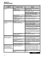
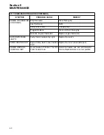
5.11 TROUBLESHOOTING GUIDE
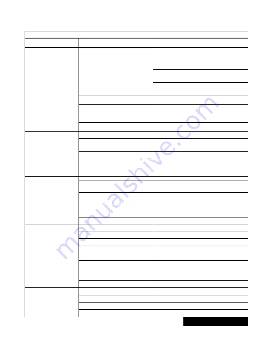
SYMPTOM
PROBABLE CAUSE
REMEDY
MPROPER UNLOADING
WITH AN EXCESSIVE
PRESSURE BUILD-UP
CAUSING PRESSURE
RELIEF VALVE TO
OPEN
(CONTINUED)
Running Blowdown Valve Pressure
Regulating Valve Set Too High
Readjust.
Leak in Control System Causing
Loss of Pressure Signal
Check control lines.
Worn seals in inlet valve. Replace seals (kit
available).
Defective pressure regulating valves; repair
valves (kits available).
Inlet Valve Jammed
Free or replace valve.
Restriction in the Control System
Check all control lines and components.
Ice and other contaminants could cause
restrictions.
Defective Pressure Relief Valve
Replace pressure relief valve.
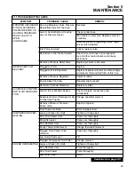
INSUFFICIENT AIR
DELIVERY
Plugged Air Filter
Replace.
Plugged Air/Fluid Separator
Replace separator element and also change
compressor fluid and fluid filter at this time.
Defective Pressure Regulator
Adjust or repair.
Engine Speed Too Low
Readjust engine speed.
Control Air Cylinder Defective
Replace cylinder.
EXCESSIVE COMPRES-
SOR FLUID CONSUMP-
TION
Leak in the Lubrication System
Check all pipes, connections and
components.
Separator Element Damaged or Not
Functioning Properly
Change separator element.
Defective Minimum Pressure/
Check Valve
Repair or replace.
Fluid Sump Overfilled
Drain to proper level.
COMPRESSOR OVER-
HEATING
Loose or Broken Fan Belt
Tighten or change belt.
Dirty Fluid Cooler Core
Clean core thoroughly.
Dirty Aftercooler
Clean core thoroughly.
Dirty Radiator Core
Clean core thoroughly.
Faulty Thermostat Element
Change thermostat element.
Plugged Fluid Cooler Tube
(Internal)
Clean tube thoroughly.
Low Sump Fluid Level
Fill.
Plugged Compressor Fluid Filter
Change element.
ENGINE OVERHEATING Loose or Broken Fan Belt
Tighten or change belt.
Dirty Radiator Core
Clean thoroughly.
Dirty Fluid Cooler
Clean thoroughly.
Low Water Level
Refill.
Summary of Contents for 1350XH
Page 6: ......
Page 18: ...Section 2 DESCRIPTION 12 Figure 2 3A Control System 900XH 1150XH and 1350XH Models...
Page 19: ...Section 2 DESCRIPTION 13 Figure 2 3B Control System Aftercooled Models...
Page 29: ...Section 2 DESCRIPTION 23 Figure 2 7 Wiring Diagram 02250145 161R01...
Page 30: ...NOTES 24...
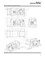
Page 33: ...Section 3 SPECIFICATIONS 27 02250135 977R03 Figure 3 2 Identification Compressor Assembly...
Page 34: ...NOTES 28...
Page 38: ...NOTES 32...
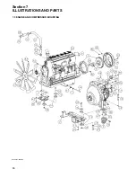
Page 54: ...Section 7 ILLUSTRATIONS AND PARTS 48 02250127 622R08 7 3 ENGINE AND COMPRESSOR MOUNTING...
Page 56: ...Section 7 ILLUSTRATIONS AND PARTS 50 02250127 622R08 7 3 ENGINE AND COMPRESSOR MOUNTING...
Page 58: ...Section 7 ILLUSTRATIONS AND PARTS 52 02250136 060R02 7 4 AIR INLET SYSTEM ALL MODELS...
Page 60: ...Section 7 ILLUSTRATIONS AND PARTS 54 02250136 060R02 7 4 AIR INLET SYSTEM ALL MODELS...
Page 62: ...Section 7 ILLUSTRATIONS AND PARTS 56 02250136 062R02 7 5 EXHAUST SYSTEM ALL MODELS...
Page 72: ...Section 7 ILLUSTRATIONS AND PARTS 66 02250127 633R02 7 7 ENGINE RADIATOR ASSEMBLY ALL MODELS...
Page 74: ...Section 7 ILLUSTRATIONS AND PARTS 68 7 8 AFTERCOOLER MOUNTING ALL MODELS 02250150 135R03...
Page 82: ...Section 7 ILLUSTRATIONS AND PARTS 76 02250140 983R01 7 12A INLET VALVE AND PARTS 6 5 900XH...
Page 86: ...Section 7 ILLUSTRATIONS AND PARTS 80 02250054 762R06 7 13A INLET VALVE PARTS 6 5 900XH...
Page 90: ...Section 7 ILLUSTRATIONS AND PARTS 84 02250127 667R10 7 14A DISCHARGE SYSTEM 900XH AND 1150XH...
Page 96: ...Section 7 ILLUSTRATIONS AND PARTS 90 02250148 288R01 7 14C DISCHARGE SYSTEM 1350XH AFTERCOOLED...
Page 98: ...Section 7 ILLUSTRATIONS AND PARTS 92 02250148 288R01 7 14C DISCHARGE SYSTEM 1350XH AFTERCOOLED...
Page 116: ...Section 7 ILLUSTRATIONS AND PARTS 110 02250164 870R01 7 19 MINIMUM PRESSURE CHECK VALVE...
Page 118: ...Section 7 ILLUSTRATIONS AND PARTS 112 02250136 066R00 7 20 FUEL SYSTEM AND PARTS ALL MODELS...
Page 120: ...Section 7 ILLUSTRATIONS AND PARTS 114 02250127 727R01 7 21 ELECTRICAL PARTS ALL MODELS...
Page 126: ...Section 7 ILLUSTRATIONS AND PARTS 120 02250136 503R02 7 23 FRAME AND PARTS...
Page 128: ...Section 7 ILLUSTRATIONS AND PARTS 122 7 24 DECAL GROUP...
Page 130: ...Section 7 ILLUSTRATIONS AND PARTS 124 7 24 DECAL GROUP...
Page 132: ...Section 7 ILLUSTRATIONS AND PARTS 126 7 24 DECAL GROUP...
Page 134: ...Section 7 ILLUSTRATIONS AND PARTS 128 7 24 DECAL GROUP...
Page 136: ...Section 7 ILLUSTRATIONS AND PARTS 130 7 25 DECAL LOCATIONS 02250136 067R03...
Page 138: ...Section 7 ILLUSTRATIONS AND PARTS 132 7 25 DECAL LOCATIONS 02250136 067R03...
Page 140: ...NOTES 134...
Page 141: ......


