Section 1
SAFETY
2
lized, chain adjustment, brake and/or electrical
interconnections)
DO NOT
interfere with or restrict
motion of any part of the compressor, including its
coupling device, with respect to the towing vehicle
when maneuvering over any anticipated terrain.
7. If provided, make sure chain length, brake and
electrical interconnections provide sufficient slack
to prevent strain when cornering and maneuvering,
yet are supported so they cannot drag or rub on
road, terrain or towing vehicle surfaces which might
cause wear that could render them inoperative.
8. On two-wheeled models, fully retract front screw
jack and any rear stabilizer legs. If a caster wheel
is provided on the screw jack it is part of the screw
jack and can not be removed. Follow the same
procedure for stowing away the wheeled jack as
you would for the standard screw jack. Pull the pin
connecting the jack to the drawbar and raise the
screw jack to its full up position. Rotate the screw
jack to its stowed position, parallel to the drawbar,
and reinsert the pin. Make sure the jack is secured
in place prior to towing.
9. Make sure tires are in good condition and are the
size (load range) specified and are inflated to the
specified pressures.
DO NOT
change the tire size
or type. Also, make sure wheel bolts, lugs or nuts
are tightened to the specified torques.
10. If provided, make sure all dual stop, tail direc-
tional and clearance lights are operating properly
and that their lenses are clean and functional. Also,
make sure all reflectors and reflecting surfaces,
including the slow moving vehicle emblem on com-
pressors provided with same, are clean and func-
tional.
11. Make sure all service air hoses (not air brake
hoses) are disconnected or are fully stowed and
secured on hose reels, if provided.
12. Make sure all access doors and tool box covers
are closed and latched. If the compressor is large
enough to hold a man, make sure all personnel are
out before closing and latching access doors.
13. Make sure parking brakes in towing vehicle are
set, or that its wheel are chocked or blocked, or that
it is otherwise restrained from moving. Then,
release the compressor parking brakes, if provided.
14. Make sure the compressor wheels are not
chocked or blocked, and that all tie-downs, if any,
are free.
15. Test running brake operation, including break-
away switch operation if provided, before attempt-
ing to tow the compressor at its rated speed or less
when conditions prevail.
16.
DO NOT
carry loose or inappropriate tools,
equipment or supplies on or in the compressor.
17.
DO NOT
load this equipment with accessories
or tools such that it is unbalanced from side to side
or front to back. Such unbalance will reduce the
towability of this equipment and may increase the
possibility of tipping, rolling over, jackknifing, etc.
Loss of control of the towing vehicle may result.
B. TOWING
1. Observe all Federal, State, and Local laws while
towing this equipment (including those specifying
minimum speed).
2.
DO NOT
exceed the towing speeds listed below
under ideal conditions. Reduce your speed accord-
ing to posted speed limits, weather, traffic, road or
terrain conditions.
a. Two axle four-wheel steerable models:
15MPH (24KMPH).
Retract the front screw jack only after
attaching the compressor to the tow
vehicle. Raise the screw jack to its full
up position and pull the pin connecting
the jack to the drawbar. Rotate the
screw jack to its stowed position, par-
allel to the drawbar, and reinsert the
pin. Make sure the jack is secured in
place prior to towing.
If a caster wheel is provided on the
screw jack it is part of the screw jack
and can not be removed. Follow the
same procedure for stowing away the
wheeled jack as you would for the stan-
dard screw jack. Pull the pin connect-
ing the jack to the drawbar and raise
the screw jack to its full up position.
Rotate the screw jack to its stowed
position, parallel to the drawbar, and
reinsert the pin. Make sure the jack is
secured in place prior to towing.
WARNING
This equipment may be tongue heavy.
DO NOT
attempt to raise or lower the
drawbar by hand if the weight is more
than you can safely handle.
WARNING
Summary of Contents for 1350XH
Page 6: ......
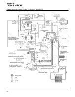
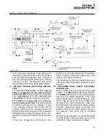
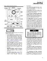
Page 18: ...Section 2 DESCRIPTION 12 Figure 2 3A Control System 900XH 1150XH and 1350XH Models...
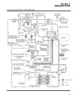
Page 19: ...Section 2 DESCRIPTION 13 Figure 2 3B Control System Aftercooled Models...
Page 29: ...Section 2 DESCRIPTION 23 Figure 2 7 Wiring Diagram 02250145 161R01...
Page 30: ...NOTES 24...
Page 33: ...Section 3 SPECIFICATIONS 27 02250135 977R03 Figure 3 2 Identification Compressor Assembly...
Page 34: ...NOTES 28...
Page 38: ...NOTES 32...
Page 54: ...Section 7 ILLUSTRATIONS AND PARTS 48 02250127 622R08 7 3 ENGINE AND COMPRESSOR MOUNTING...
Page 56: ...Section 7 ILLUSTRATIONS AND PARTS 50 02250127 622R08 7 3 ENGINE AND COMPRESSOR MOUNTING...
Page 58: ...Section 7 ILLUSTRATIONS AND PARTS 52 02250136 060R02 7 4 AIR INLET SYSTEM ALL MODELS...
Page 60: ...Section 7 ILLUSTRATIONS AND PARTS 54 02250136 060R02 7 4 AIR INLET SYSTEM ALL MODELS...
Page 62: ...Section 7 ILLUSTRATIONS AND PARTS 56 02250136 062R02 7 5 EXHAUST SYSTEM ALL MODELS...
Page 72: ...Section 7 ILLUSTRATIONS AND PARTS 66 02250127 633R02 7 7 ENGINE RADIATOR ASSEMBLY ALL MODELS...
Page 74: ...Section 7 ILLUSTRATIONS AND PARTS 68 7 8 AFTERCOOLER MOUNTING ALL MODELS 02250150 135R03...
Page 82: ...Section 7 ILLUSTRATIONS AND PARTS 76 02250140 983R01 7 12A INLET VALVE AND PARTS 6 5 900XH...
Page 86: ...Section 7 ILLUSTRATIONS AND PARTS 80 02250054 762R06 7 13A INLET VALVE PARTS 6 5 900XH...
Page 90: ...Section 7 ILLUSTRATIONS AND PARTS 84 02250127 667R10 7 14A DISCHARGE SYSTEM 900XH AND 1150XH...
Page 96: ...Section 7 ILLUSTRATIONS AND PARTS 90 02250148 288R01 7 14C DISCHARGE SYSTEM 1350XH AFTERCOOLED...
Page 98: ...Section 7 ILLUSTRATIONS AND PARTS 92 02250148 288R01 7 14C DISCHARGE SYSTEM 1350XH AFTERCOOLED...
Page 116: ...Section 7 ILLUSTRATIONS AND PARTS 110 02250164 870R01 7 19 MINIMUM PRESSURE CHECK VALVE...
Page 118: ...Section 7 ILLUSTRATIONS AND PARTS 112 02250136 066R00 7 20 FUEL SYSTEM AND PARTS ALL MODELS...
Page 120: ...Section 7 ILLUSTRATIONS AND PARTS 114 02250127 727R01 7 21 ELECTRICAL PARTS ALL MODELS...
Page 126: ...Section 7 ILLUSTRATIONS AND PARTS 120 02250136 503R02 7 23 FRAME AND PARTS...
Page 128: ...Section 7 ILLUSTRATIONS AND PARTS 122 7 24 DECAL GROUP...
Page 130: ...Section 7 ILLUSTRATIONS AND PARTS 124 7 24 DECAL GROUP...
Page 132: ...Section 7 ILLUSTRATIONS AND PARTS 126 7 24 DECAL GROUP...
Page 134: ...Section 7 ILLUSTRATIONS AND PARTS 128 7 24 DECAL GROUP...
Page 136: ...Section 7 ILLUSTRATIONS AND PARTS 130 7 25 DECAL LOCATIONS 02250136 067R03...
Page 138: ...Section 7 ILLUSTRATIONS AND PARTS 132 7 25 DECAL LOCATIONS 02250136 067R03...
Page 140: ...NOTES 134...
Page 141: ......


