Section 1
SAFETY
3
b. All other models: 55 MPH (88KMPH).
3. Remember that the portable air compressor may
approach or exceed the weight of the towing vehi-
cle. Maintain increased stopping distances accord-
ingly.
DO NOT
make sudden lane changes, U-
turns, or other maneuvers. Such maneuvers can
cause the compressor to tip, roll over, jackknife or
slide and cause loss of control of the towing vehicle.
Tipping, rolling over, etc. can occur suddenly with-
out warning. U-turns especially should be made
slowly and carefully.
4. Avoid grades in excess of 15° (27%).
5. Avoid potholes, rocks and other obstructions, and
soft shoulders or unstable terrain.
6. Maneuver in a manner that will not exceed the
freedom of motion of the compressor’s drawbar
and/or coupling device, in or on the towing vehicle’s
coupling device and/or adjacent structure whether
towing forward or backing up, regardless of the ter-
rain being traversed.
7.
DO NOT
permit personnel to ride in or on the
compressor.
8. Make sure the area behind, in front of, and under
the compressor is clear of all personnel and
obstructions prior to towing in any direction.
9.
DO NOT
permit personnel to stand or ride on the
drawbar, or to stand or walk between the compres-
sor and the towing vehicle.
C. PARKING OR LOCATING COMPRESSOR
1. Park or locate compressor on a level surface, if
possible. If not, park or locate compressor across
grade so the compressor does not tend to roll
downhill.
DO NOT
park or locate compressor on
grades exceeding 15° (27%).
2. Make sure compressor is parked or located on a
firm surface than can support its weight.
3. Park or locate compressor so the wind, if any,
tends to carry the exhaust fumes and radiator heat
away from the compressor air inlet openings, and
also where the compressor will not be exposed to
excessive dust from the work site.
4. On four-wheel models, park compressor with
front wheels in straight ahead position.
5. Set parking brakes and disconnect breakaway
switch cable and all other interconnecting electrical
and/or brake connections, if provided.
6. Block or chock both sides of all wheels.
7. If provided, unhook chains and remove them
from the points of chain attachment on the towing
vehicle, then hook chains to bail on drawbar or wrap
chains around the drawbar and hook them to them-
selves to keep chains off the ground which might
accelerate rusting.
8. Lower front screw jack and/or any front and rear
stabilizer legs. Make sure the surface they contact
has sufficient load bearing capability to support the
weight of the compressor.
9. If a caster wheel is provided on the screw jack it
is part of the screw jack and can not be removed.
Follow the same procedure for stowing away the
wheeled jack as you would for the standard screw
jack. Raise the screw jack to its full up position and
pull the pin connecting the jack to the drawbar.
Rotate the screw jack to its stowed position, paral-
lel to the drawbar, and reinsert the pin. Make sure
the jack is secured in place prior to towing.
10. Disconnect coupling device, keeping hands and
fingers clear of all pinch points. If the compressor is
provided with a drawbar,
DO NOT
attempt to lift the
This equipment may be tongue heavy.
DO NOT
attempt to raise or lower the
drawbar by hand if the weight is more
than you can safely handle.
Retract the front screw jack only after
attaching the compressor to the tow
vehicle. Raise the screw jack to its full
up position and pull the pin connecting
the jack to the drawbar. Rotate the
screw jack to its stowed position, par-
allel to the drawbar, and reinsert the
pin. Make sure the jack is secured in
place prior to towing.
If a caster wheel is provided on the
screw jack it is part of the screw jack
and can not be removed. Follow the
same procedure for stowing away the
wheeled jack as you would for the stan-
dard screw jack. Pull the pin connect-
ing the jack to the drawbar and raise
the screw jack to its full up position.
Rotate the screw jack to its stowed
position, parallel to the drawbar, and
reinsert the pin. Make sure the jack is
secured in place prior to towing.
WARNING
WARNING
Summary of Contents for 1350XH
Page 6: ......
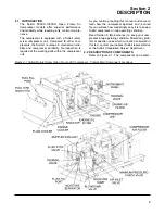
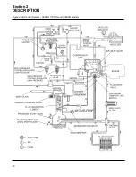
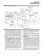
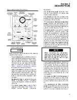
Page 18: ...Section 2 DESCRIPTION 12 Figure 2 3A Control System 900XH 1150XH and 1350XH Models...
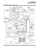
Page 19: ...Section 2 DESCRIPTION 13 Figure 2 3B Control System Aftercooled Models...
Page 29: ...Section 2 DESCRIPTION 23 Figure 2 7 Wiring Diagram 02250145 161R01...
Page 30: ...NOTES 24...
Page 33: ...Section 3 SPECIFICATIONS 27 02250135 977R03 Figure 3 2 Identification Compressor Assembly...
Page 34: ...NOTES 28...
Page 38: ...NOTES 32...
Page 54: ...Section 7 ILLUSTRATIONS AND PARTS 48 02250127 622R08 7 3 ENGINE AND COMPRESSOR MOUNTING...
Page 56: ...Section 7 ILLUSTRATIONS AND PARTS 50 02250127 622R08 7 3 ENGINE AND COMPRESSOR MOUNTING...
Page 58: ...Section 7 ILLUSTRATIONS AND PARTS 52 02250136 060R02 7 4 AIR INLET SYSTEM ALL MODELS...
Page 60: ...Section 7 ILLUSTRATIONS AND PARTS 54 02250136 060R02 7 4 AIR INLET SYSTEM ALL MODELS...
Page 62: ...Section 7 ILLUSTRATIONS AND PARTS 56 02250136 062R02 7 5 EXHAUST SYSTEM ALL MODELS...
Page 72: ...Section 7 ILLUSTRATIONS AND PARTS 66 02250127 633R02 7 7 ENGINE RADIATOR ASSEMBLY ALL MODELS...
Page 74: ...Section 7 ILLUSTRATIONS AND PARTS 68 7 8 AFTERCOOLER MOUNTING ALL MODELS 02250150 135R03...
Page 82: ...Section 7 ILLUSTRATIONS AND PARTS 76 02250140 983R01 7 12A INLET VALVE AND PARTS 6 5 900XH...
Page 86: ...Section 7 ILLUSTRATIONS AND PARTS 80 02250054 762R06 7 13A INLET VALVE PARTS 6 5 900XH...
Page 90: ...Section 7 ILLUSTRATIONS AND PARTS 84 02250127 667R10 7 14A DISCHARGE SYSTEM 900XH AND 1150XH...
Page 96: ...Section 7 ILLUSTRATIONS AND PARTS 90 02250148 288R01 7 14C DISCHARGE SYSTEM 1350XH AFTERCOOLED...
Page 98: ...Section 7 ILLUSTRATIONS AND PARTS 92 02250148 288R01 7 14C DISCHARGE SYSTEM 1350XH AFTERCOOLED...
Page 116: ...Section 7 ILLUSTRATIONS AND PARTS 110 02250164 870R01 7 19 MINIMUM PRESSURE CHECK VALVE...
Page 118: ...Section 7 ILLUSTRATIONS AND PARTS 112 02250136 066R00 7 20 FUEL SYSTEM AND PARTS ALL MODELS...
Page 120: ...Section 7 ILLUSTRATIONS AND PARTS 114 02250127 727R01 7 21 ELECTRICAL PARTS ALL MODELS...
Page 126: ...Section 7 ILLUSTRATIONS AND PARTS 120 02250136 503R02 7 23 FRAME AND PARTS...
Page 128: ...Section 7 ILLUSTRATIONS AND PARTS 122 7 24 DECAL GROUP...
Page 130: ...Section 7 ILLUSTRATIONS AND PARTS 124 7 24 DECAL GROUP...
Page 132: ...Section 7 ILLUSTRATIONS AND PARTS 126 7 24 DECAL GROUP...
Page 134: ...Section 7 ILLUSTRATIONS AND PARTS 128 7 24 DECAL GROUP...
Page 136: ...Section 7 ILLUSTRATIONS AND PARTS 130 7 25 DECAL LOCATIONS 02250136 067R03...
Page 138: ...Section 7 ILLUSTRATIONS AND PARTS 132 7 25 DECAL LOCATIONS 02250136 067R03...
Page 140: ...NOTES 134...
Page 141: ......


