Section 7
ILLUSTRATIONS AND PARTS
87
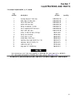
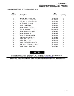
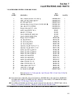
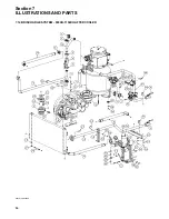
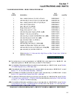
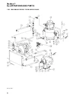
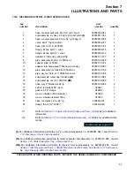
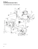
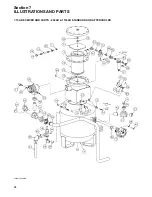
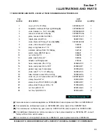
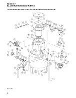
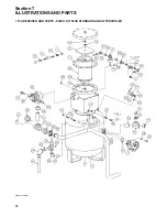
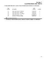
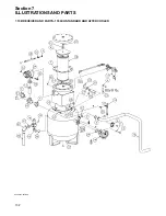
7.14B DISCHARGE SYSTEM - 900XH-1150XH AFTERCOOLED
key
part
number
description
number
quantity
1
hose, medium pressure .25 x 86” w/37 swvls
02250054-261
1
2
sub assembly, vlv assy 2.5 npt x 2.5 4bsf disch
(I)
02250081-044
1
3
hose, medium pressure 5/16 x 54” lg 37deg st
02250083-838
1
4
valve, ball 2” fnpt w/o drain
02250086-337
3
5
hose, disch 2.5” st stl 900xh
02250092-744
1
6
flange, kit sae splt 2” - viton
02250099-415
5
7
flange, kit sae splt 2.5” - viton
02250099-416
1
8
sub assembly, water trap assy 900xh ac
(II)
02250131-654
1
9
adapter, 2” tube assy w/4-bolt flg
02250131-977
2
10
sub assembly, air control manifold 900xh tier ii
(III)
02250132-421
1
11
sub assembly, speed control tier ii
(IV)
02250132-481
1
12
pipe, assembly trap/svr vlv 900xh ac
02250133-469
1
13
support, pipe cs 900xh
02250133-724
1
14
sub assembly, inlet valve 8” 1150/350
(V)
02250134-299
1
15
support, discharge pipe 1150xha w/o canopy
02250139-929
1
16
sub assembly, receiver cat 1150xha w/o canopy
(VI)
02250139-932
1
17
pipe, assembly rec tank/aftclr 900xhh ac
02250142-706
1
A1
Refer to
High Pressure Filter / Check Valve / Orifice
for
additional information.
(I)
For maintenance on valve sub-assembly no. 02250081-044, order repair kit no. 606208-001, and
replacement gasket no. 046053 (refer to key number 21 of this Section).
(II)
For additional information pertaining to water trap sub-assembly no. 02250131-654, consult
7.16, Water Separator Trap - Aftercooled Only
(III)
For additional information pertaining to air control manifold sub-assembly no. 02250132-421, consult
Section 7.11, Air Control Manifold Assembly - All Models
(IV)
For additional information pertaining to speed control sub-assembly no. 02250132-481, consult
ection 7.10, Speed Control Cylinder and Parts - All Models
(V)
For additional information pertaining to inlet valve sub-assembly no. 02250134-299, consult
7.12B, Inlet Valve and Parts (8”) - 1150XH-1350XH
for external parts, and
and Parts - 8” - 1150XH-1350XH
(VI)
For additional information pertaining to receiver sub-assembly no. 02250139-932, consult
7.15B, Receiver and Parts - 1350XH Standard and Aftercooled
High Pressure Filter / Check Valve / Orifice
PLEASE NOTE: WHEN ORDERING PARTS, INDICATE THE SERIAL NUMBER OF COMPRESSOR
Summary of Contents for 1350XH
Page 6: ......
Page 18: ...Section 2 DESCRIPTION 12 Figure 2 3A Control System 900XH 1150XH and 1350XH Models...
Page 19: ...Section 2 DESCRIPTION 13 Figure 2 3B Control System Aftercooled Models...
Page 29: ...Section 2 DESCRIPTION 23 Figure 2 7 Wiring Diagram 02250145 161R01...
Page 30: ...NOTES 24...
Page 33: ...Section 3 SPECIFICATIONS 27 02250135 977R03 Figure 3 2 Identification Compressor Assembly...
Page 34: ...NOTES 28...
Page 38: ...NOTES 32...
Page 54: ...Section 7 ILLUSTRATIONS AND PARTS 48 02250127 622R08 7 3 ENGINE AND COMPRESSOR MOUNTING...
Page 56: ...Section 7 ILLUSTRATIONS AND PARTS 50 02250127 622R08 7 3 ENGINE AND COMPRESSOR MOUNTING...
Page 58: ...Section 7 ILLUSTRATIONS AND PARTS 52 02250136 060R02 7 4 AIR INLET SYSTEM ALL MODELS...
Page 60: ...Section 7 ILLUSTRATIONS AND PARTS 54 02250136 060R02 7 4 AIR INLET SYSTEM ALL MODELS...
Page 62: ...Section 7 ILLUSTRATIONS AND PARTS 56 02250136 062R02 7 5 EXHAUST SYSTEM ALL MODELS...
Page 72: ...Section 7 ILLUSTRATIONS AND PARTS 66 02250127 633R02 7 7 ENGINE RADIATOR ASSEMBLY ALL MODELS...
Page 74: ...Section 7 ILLUSTRATIONS AND PARTS 68 7 8 AFTERCOOLER MOUNTING ALL MODELS 02250150 135R03...
Page 82: ...Section 7 ILLUSTRATIONS AND PARTS 76 02250140 983R01 7 12A INLET VALVE AND PARTS 6 5 900XH...
Page 86: ...Section 7 ILLUSTRATIONS AND PARTS 80 02250054 762R06 7 13A INLET VALVE PARTS 6 5 900XH...
Page 90: ...Section 7 ILLUSTRATIONS AND PARTS 84 02250127 667R10 7 14A DISCHARGE SYSTEM 900XH AND 1150XH...
Page 96: ...Section 7 ILLUSTRATIONS AND PARTS 90 02250148 288R01 7 14C DISCHARGE SYSTEM 1350XH AFTERCOOLED...
Page 98: ...Section 7 ILLUSTRATIONS AND PARTS 92 02250148 288R01 7 14C DISCHARGE SYSTEM 1350XH AFTERCOOLED...
Page 116: ...Section 7 ILLUSTRATIONS AND PARTS 110 02250164 870R01 7 19 MINIMUM PRESSURE CHECK VALVE...
Page 118: ...Section 7 ILLUSTRATIONS AND PARTS 112 02250136 066R00 7 20 FUEL SYSTEM AND PARTS ALL MODELS...
Page 120: ...Section 7 ILLUSTRATIONS AND PARTS 114 02250127 727R01 7 21 ELECTRICAL PARTS ALL MODELS...
Page 126: ...Section 7 ILLUSTRATIONS AND PARTS 120 02250136 503R02 7 23 FRAME AND PARTS...
Page 128: ...Section 7 ILLUSTRATIONS AND PARTS 122 7 24 DECAL GROUP...
Page 130: ...Section 7 ILLUSTRATIONS AND PARTS 124 7 24 DECAL GROUP...
Page 132: ...Section 7 ILLUSTRATIONS AND PARTS 126 7 24 DECAL GROUP...
Page 134: ...Section 7 ILLUSTRATIONS AND PARTS 128 7 24 DECAL GROUP...
Page 136: ...Section 7 ILLUSTRATIONS AND PARTS 130 7 25 DECAL LOCATIONS 02250136 067R03...
Page 138: ...Section 7 ILLUSTRATIONS AND PARTS 132 7 25 DECAL LOCATIONS 02250136 067R03...
Page 140: ...NOTES 134...
Page 141: ......


