Section 3
SPECIFICATIONS
18
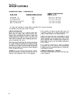
LUBRICATION GUIDE -- COMPRESSOR
FLUID TYPE
CHANGE PERIOD, HOURS
AMBIENT TEMPERATURE
RANGE
_
F (
_
C)
Sullair AWF
1200
---20 to 120 (---29 to 49)
D---A Torque Fluid
SAE10W SE, SF, SG, CD
MIL---L---2104E 10W
300
300
10 to 110 (---12 to 43)
0 to 100 (---18 to 38)
0 to 100 (---18 to 38)
300
(I)
(I)
Sullair part numbers for Sullair AWF are 250030---757 (5 gallons/20 liters)
and 250030---758 (55 gallon drum/115 liters).
APPLICATION GUIDE
Sullair Air Compressors are supplied with Sullair
AWF which is heavy duty multi---viscosity, all---
weather fluid. Sullair AWF also allows an extended
change interval. Detergent motor oils (SAE 10W
Class SE,SF, SG or CD) can also be used. Any of
these oils are suitable under conditions where se-
vere oil oxidations can occur.
Water must be drained from the receiver periodical-
ly. In high ambient temperature and high humidity
conditions, condensed moisture may emulsify with
the oil forming a
“
milky” color. SAE 10W is especially
prone to this condition. The fluid should be changed
if this condition develops.
DO NOT
mix types of fluids. Combinations of differ-
ent fluids may lead to operational problems such as
foaming, filter plugging, orifice or line plugging.
When ambient conditions exceed those noted or if
conditions warrant use of other extended life lubri-
cants, contact Sullair for recommendations.
Sullair encourages the user to participate in a fluid
analysis program. This could result in a fluid change
interval differing from that stated in the manual. Sul-
lair Corporation offers a fluid analysis program for
Sullair AWF. Contact your local Sullair representa-
tive for details.
D---A Lubricant
r
Company Inc. offers an analysis
program for users of D---A products and Sullair AWF.
Contact your D---A lubricant supplier or Sullair rep-
resentative for details.
LUBRICATION GUIDE -- ENGINE
For engine oil specifications, refer to the Engine Op-
erator’s Manual.
Summary of Contents for 175
Page 6: ...NOTES ...
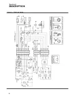
Page 22: ...Section 2 DESCRIPTION 16 Figure 2 7 Electrical System ...
Page 52: ...Section 7 ILLUSTRATIONS AND PARTS LIST 46 7 4A RADIATOR COMPRESSOR FLUID SYSTEM 175 MODELS ...
Page 54: ...Section 7 ILLUSTRATIONS AND PARTS LIST 48 7 4A RADIATOR COMPRESSOR FLUID SYSTEM 175 MODELS ...
Page 78: ...Section 7 ILLUSTRATIONS AND PARTS LIST 72 7 9B ELECTRICAL PARTS 185 185H MODELS ...
Page 80: ...Section 7 ILLUSTRATIONS AND PARTS LIST 74 7 10 INSTRUMENT PANEL PARTS ALL MODELS ...
Page 82: ...Section 7 ILLUSTRATIONS AND PARTS LIST 76 7 11A AIR INLET AND EXHAUST 175 MODELS ...
Page 84: ...Section 7 ILLUSTRATIONS AND PARTS LIST 78 7 11B AIR INLET AND EXHAUST 185 185H MODELS ...
Page 86: ...Section 7 ILLUSTRATIONS AND PARTS LIST 80 7 12 FUEL TANK CONNECTIONS ALL MODELS ...
Page 88: ...Section 7 ILLUSTRATIONS AND PARTS LIST 82 7 13A CANOPY PARTS 175 MODELS ...
Page 90: ...Section 7 ILLUSTRATIONS AND PARTS LIST 84 7 13B CANOPY PARTS 185 185H MODELS ...
Page 92: ...Section 7 ILLUSTRATIONS AND PARTS LIST 86 7 14 DECALS ...
Page 94: ...Section 7 ILLUSTRATIONS AND PARTS LIST 88 7 14 DECALS ...
Page 96: ...Section 7 ILLUSTRATIONS AND PARTS LIST 90 7 14 DECALS ...
Page 99: ......

