background image

Section 7

ILLUSTRATIONS AND PARTS LIST

105

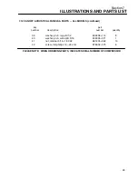
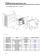
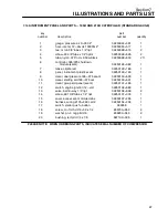
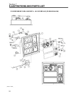
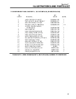
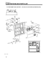
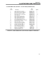
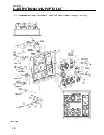
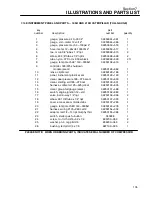
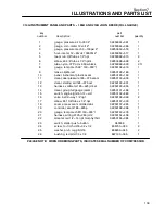
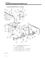
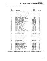
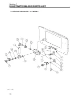
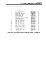
7.14E INSTRUMENT PANEL AND PARTS -- 185H AND 210H CATERPILLAR (FULL GAUGE)

key

part

number

description

number

quantity

1

gauge, pressure air 0---300 2”

02250044---361

1

2

gauge, volt---meter 12 volt 2”

02250044---366

1

3

gauge, pressure mech 0---100psi 2”

02250050---516

1

4

hour---meter, 12---24vdc 10000hr 2”

02250050---517

1

5

tee, m run 3/8”tube x 1/4”npt

02250099---615

2

6

elbow, 90 3/8”tube x 1/4”npt m

02250099---626

2

7

tube, nylon .375”od x .050w black

02250099---630

2 ft

8

gauge, temp mech 48” 140---300$sf

02250102---619

1

9

controller, 185/375 shutdown

module (ssam)

02250126---682

1

10

lense, cliplite led

02250129---189

1

11

panel, instrument plastic ssam

02250129---190

1

12

decal, dual pressure 185---375 ssam

02250130---630

1

13

decal, starting aid 185---375 cat

02250130---631

1

14

harness, voltmeter 125---425 jd/cat

02250130---635

1

15

decal, group full gauge (ssam)

02250131---486

1

16

switch, engine ignition 12---volt

02250132---883

1

17

valve, ball 2---way 1/4”npt

02250136---999

2

18

elbow, 90 f 3/8”tube x 1/4”npt

02250137---033

1

19

cover, access ssam molded abs

02250137---265

1

20

gauge, temp mech 8ft 140---300$sf

02250143---278

1

21

harness, wiring 210h---260 cat t2

02250154---334

1

22

adapter, red 1/2---14 npt murphy thrd

02250155---384

1

23

switch, starter push---button

040038

1

24

screw, tc---f rd hd #6---32 x 1/2

835700---050

2

25

washer, pl---b reg pltd #6

838200---045

2

26

bushing, red pltd 1/4 x 1/8

867100---005

1

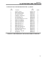
PLEASE NOTE: WHEN ORDERING PARTS, INDICATE SERIAL NUMBER OF COMPRESSOR

Summary of Contents for 185H

Page 1: ...llair Corporation KEEP FOR FUTURE REFERENCE The information in this document is correct at the time of printing for Portable Compressor Serial Number 004 150300 and all subsequent Serial Numbers PORTA...

Page 2: ...igan City Indiana Instruction includes discussion of the function and installation of Sullair service parts troubleshooting of the most common problems and actual equipment operation The seminars are...

Page 3: ...COMPONENTS 10 2 3 SULLAIR COMPRESSOR UNIT FUNCTIONAL DESCRIPTION 11 2 4 COMPRESSOR COOLING AND LUBRICATION SYSTEM FUNCTIONAL DESCRIPTION 11 2 5 COMPRESSOR DISCHARGE SYSTEM FUNCTIONAL DESCRIPTION 12 2...

Page 4: ...FILTER MAINTENANCE 29 SPEARATOR ELEMENT REPLACEMENT 29 PROCEDURE FOR SETTING SPEED AND PRESSURE CONTROLS ON PORTABLE COMPRESSOR WITH POPPET VALVE 31 BEARING LUBRICATION 31 5 8 TROUBLESHOOTING INTRODU...

Page 5: ...96 7 14A INSTRUMENT PANEL AND PARTS 185H AND 210H CATERPILLAR STANDARD GAUGE 98 7 14B INSTRUMENT PANEL AND PARTS 260 CATERPILLAR STANDARD GAUGE 100 7 14C INSTRUMENT PANEL AND PARTS 185H AND 210H JOHN...

Page 6: ......

Page 7: ...racked bent dented or otherwise deformed or degraded and iii loose nuts bolts or other fasteners Should any such condition be present DO NOT TOW until the problem is corrected 2 Back the tow vehicle t...

Page 8: ...ons prevail 16 DO NOT carry loose or inappropriate tools equipment or supplies on or in the compressor 17 DO NOT load this equipment with accesso ries or tools such that it is unbalanced from side to...

Page 9: ...ift or raise the drawbar without avoiding injury to yourself or others 11 When possible stow hinged drawbar in the vertical upright position Make certain it is se curely latched in the vertical uprigh...

Page 10: ...permit liquids including air line anti icer system antifreeze compound or fluid film to ac cumulate on bottom covers or on under or around acoustical material or on any external or internal surfaces...

Page 11: ...aid cylinders G Disconnect the grounded negative battery con nection to prevent accidental engine operation prior to attempting repairs or adjustments Tag the battery connection so others will not une...

Page 12: ...nd DO NOT contact any other portion of the compressor when making adjustments or repairs to exposed live parts of the electrical system C Attempt repairs only in clean dry and well lighted and ventila...

Page 13: ...terminals are usually identified by a plus sign on the terminal and the letters POS adjacent to the terminal Negative battery ter minals are usually identified by the letters NEG ad jacent to the term...

Page 14: ...8 NOTES...

Page 15: ...his text contact your nearest Sullair representative or the Sullair Corporation Service Department 2 2 DESCRIPTION OF COMPONENTS Refer to Figures 2 1 The components and assem blies of the Sullair Port...

Page 16: ...r high capacity fan and thermostat The high ca pacity fan pushes air through the radiator keeping the engine at the proper operating temperature The same fan also cools the fluid in the compressor coo...

Page 17: ...unit bypassing the cooler As the compressor continues to operate the temperature of the fluid rises and the thermostatic control opens allowing a portion of the fluid to the cooler When the temperatur...

Page 18: ...wdown valve and tubing con necting the various components to the compres sor and engine governor The functional descrip tions of the control system are given in four distinct phases of operation It ap...

Page 19: ...Section 2 DESCRIPTION 13 Figure 2 4A Control System with Piping and Instrumentation 185H 210H Models...

Page 20: ...Section 2 DESCRIPTION 14 Figure 2 4B Control System with Piping and Instrumentation 260 Models...

Page 21: ...to vent the sump pres sure to the atmosphere 2 7 AIR INLET SYSTEM FUNCTIONAL DESCRIP TION Refer to Figure 2 5 The air inlet system consists of two air filters a compressor air inlet valve and in terc...

Page 22: ...ed OFF The flash codes are as follows 1 flash high compressor temperature 2 flashes high engine coolant temperature 3 flashes low engine oil pressure 4 flashes low engine speed 5 flashes low fuel leve...

Page 23: ...Section 2 DESCRIPTION 17 Figure 2 6 Instrument Panel Group...

Page 24: ...Section 2 DESCRIPTION 18 Figure 2 7 Electrical System JOHN DEERE 02250144 446R05...

Page 25: ...Section 2 DESCRIPTION 19 Figure 2 7A Electrical System CATERPILLAR P02250144 395R04...

Page 26: ...20 NOTES...

Page 27: ...250_F Temp 121_C 121_C 121_C Service Valves 2 3 4 2 3 4 2 3 4 Maximum Towing Speed 55 mph 88 kmph 55 mph 88 kmph 55 mph 88 kmph Axle Rating 3500 lbs 1588 kg 3500 lbs 1588 kg 3500 lbs 1588 kg Rated Pr...

Page 28: ...250_F Temp 121_C 121_C 121_C Service Valves 2 3 4 2 3 4 2 3 4 Maximum Towing Speed 55 mph 88 kmph 55 mph 88 kmph 55 mph 88 kmph Axle Rating 3500 lbs 1588 kg 3500 lbs 1588 kg 3500 lbs 1588 kg Rated Pre...

Page 29: ...dity conditions condensed moisture may emulsify with the oil forming a milky color SAE 10W is especially prone to this condition The fluid should be changed if this condition develops DO NOT mix types...

Page 30: ...24 NOTES...

Page 31: ...ted hours of operation Useful for planning and logging service schedules FLUID LEVEL SIGHT GLASS Monitors the fluid level in the sump Proper level is visible halfway up the sight glass Check the level...

Page 32: ...nitial run shut the compressor down and refill the radiator and compressor fluid sump as re quired Tighten any loose fittings and check fan belt tension I The radiator is filled with a 50 50 mixture o...

Page 33: ...peration a few mainte nance requirements are needed to rid the system of any foreign materials Perform the following mainte nance operations to prevent unnecessary prob lems 1 Clean the return line or...

Page 34: ...Figure 5 1 1 Using a strap wrench remove the old element 2 Clean the gasket seating surface 3 Apply a light film of fluid to the new gasket 4 Hand tighten the new element from kit P N 250028 032 until...

Page 35: ...the separator ele ment This will assure the proper fluid return flow 9 Clean the fluid return line strainer and clear the orifice prior to restarting the compressor 10 After 24 hours of operation tig...

Page 36: ...Section 5 MAINTENANCE 30 Figure 5 4 Control System Adjustment 185H 210 MODELS 260 MODELS...

Page 37: ...ur por table compressor axle Wheel bearings should be lubricated at least once every 12 months or more frequently to help insure proper performance Use wheel bearing grease that conforms to military s...

Page 38: ...ecked instrument panel connectors and disconnected reattach if required Check instrument panel wires for broken connections or corrosion Clean and or replace if required Faulty SSAM module Replace the...

Page 39: ...if necessary Cooling air flow is insufficient Clean cooler and check for proper ventilation Low compressor fluid sump level Add fluid as required Clogged compressor fluid filter Change filter element...

Page 40: ...RELIEF VALVE TO OPEN Pressure Regulating Valve Is Set Readjust Too High Leak In Control System Causing Check control lines Loss Of Pressure Signal Defective pressure regulating valve repair valve kit...

Page 41: ...y COMPRESSOR OVERHEATING Low Sump Fluid Level Fill Loose Or Broken Fan Belt Tighten or change belt Dirty Fluid Cooler Core Clean core thoroughly Plugged Compressor Fluid Filter Change element Faulty T...

Page 42: ...36 NOTES...

Page 43: ...ed or ren dered inoperative by any person Among those acts included in the prohibition against tampering are the acts listed below 1 Removal or rendering inoperative any of the fol lowing a Engine exh...

Page 44: ...sor with defective air inlet system Remove and replace defective parts by ordering with part numbers indicated in the Parts List Maintenance Performed By Location Date Maintenance Performed By Locatio...

Page 45: ...ed in Parts List Maintenance Performed By Location Date Maintenance Performed By Location Date DDDDDDDDDDDDDDDDD 5 ANNUAL ACOUSTICAL MATERIALS INSPECTION At least annually inspect all acoustical mater...

Page 46: ...ly operate compressor and inspect to make sure all systems are operating properly and that engine runs at rated speed and pressure DO NOT operate malfunctioning or improperly adjusted compressor Repai...

Page 47: ..._______________________________________________________________ SULLAIR EUROPE S A SULLAIR CORPORATION 3700 East Michigan Boulevard Michigan City Indiana 46360 U S A or 1 219 879 5451 SULLAIR ASIA LTD...

Page 48: ...tor blowdown valve manifold 02250147 737 1 11 kit repair for pressure regulator valve 250017 280 250019 453 1 12 maintenance for minimum pressure check valve no 02250088 349 S repair kit 250026 758 1...

Page 49: ...Section 7 ILLUSTRATIONS AND PARTS LIST 43 NOTES...

Page 50: ...Section 7 ILLUSTRATIONS AND PARTS LIST 44 7 3A ENGINE COMPRESSOR PARTS 185H 210H CATERPILLAR 02250149 637R02...

Page 51: ...7 cover eng pto 185h 260 cat 02250150 197 1 18 gasket eng pto 185h 260 cat 02250150 198 1 19 orifice 062 x 25m x 25m nptf 027443 1 20 clamp hose 13 16 to 1 1 2 040513 1 21 joint ball female 1 4 l h 25...

Page 52: ...Section 7 ILLUSTRATIONS AND PARTS LIST 46 7 3A ENGINE COMPRESSOR PARTS 185H 210H CATERPILLAR 02250149 637R02...

Page 53: ...pltd 1 4 20 x 1 1 2 867304 150 1 46 nut hex jam rh pltd 1 4 28 868204 164 2 47 connector 45 deg str x jic 1 7 8 x 1 7 8 870524 024 1 48 connector 90d str x jic 1 1 16 x 1 1 16 870612 012 1 49 adapter...

Page 54: ...Section 7 ILLUSTRATIONS AND PARTS LIST 48 7 3B ENGINE COMPRESSOR PARTS 260 CATERPILLAR 02250149 631R02...

Page 55: ...ries unit II 1 22 joint ball female 1 4 l h 250011 578 1 23 joint ball female 1 4 r h 250011 597 1 24 elbow 1 4 tube x 1 4 npt 250018 430 1 25 spacer air conn vlv 250q 250022 950 1 26 cylinder speed 3...

Page 56: ...Section 7 ILLUSTRATIONS AND PARTS LIST 50 7 3B ENGINE COMPRESSOR PARTS 260 CATERPILLAR 02250149 631R02...

Page 57: ...w hex gr5 1 2 13 x 1 1 4 829108 125 4 42 capscrew hex gr5 1 2 13 x 3 1 4 829108 325 4 43 capscrew hex gr5 5 8 11 x 1 1 4 829110 125 4 44 screw socket iso 4762 m10 x 40mm 829310 040 8 45 washer spr loc...

Page 58: ...Section 7 ILLUSTRATIONS AND PARTS LIST 52 7 3C ENGINE COMPRESSOR PARTS 185H 210H JOHN DEERE 02250149 639R02...

Page 59: ...185h 260 jd 02250148 498 1 18 valve eng oil drain m22x1 5 02250148 791 1 19 spacer fan 3 50lg 2 5bc 185h jd 02250148 826 1 20 clip spring spd ctl 185 260 02250152 418 1 21 support spd ctl 185 260 jd...

Page 60: ...Section 7 ILLUSTRATIONS AND PARTS LIST 54 7 3C ENGINE COMPRESSOR PARTS 185H 210H JOHN DEERE 02250149 639R02...

Page 61: ...ferry head hd pltd 1 4 20 x 1 1 2 867304 150 1 49 capscrew ferry head hd pltd 3 8 16 x 1 1 2 867306 150 8 50 nut hex jam rh pltd 1 4 28 868204 164 1 51 nut hex jam rh pltd 5 16 24 868205 195 1 52 conn...

Page 62: ...Section 7 ILLUSTRATIONS AND PARTS LIST 56 7 3D ENGINE COMPRESSOR PARTS 260 JOHN DEERE 02250149 634R02...

Page 63: ...85 260 jd 02250152 439 1 22 orifice 062 x 25m x 25m nptf 027443 1 23 rod end spherical rh 5 16 040136 1 24 clamp hose 1 2 043197 1 25 compr model 12 series unit III 1 26 joint ball female 1 4 l h 2500...

Page 64: ...Section 7 ILLUSTRATIONS AND PARTS LIST 58 7 3D ENGINE COMPRESSOR PARTS 260 JOHN DEERE continued 02250149 634R02...

Page 65: ...5 1 2 13 x 1 1 4 829108 125 4 45 capscrew hex gr5 1 2 13 x 3 1 4 829108 325 4 46 capscrew hex gr5 5 8 11 x 1 1 4 829110 125 4 47 washer spr lock reg pltd 1 2 837808 125 8 48 washer spr lock reg pltd 5...

Page 66: ...Section 7 ILLUSTRATIONS AND PARTS LIST 60 7 4A AIR INLET AND EXHAUST ALL CATERPILLAR MODELS 02250149 632R00...

Page 67: ...ca 02250149 252 1 14 gasket exhaust 185h 260 pe cat 02250149 406 1 15 shield heat fuel tank 185h cat 02250151 050 1 16 clamp hose 1 13 16 x 2 3 4 adj 40083 1 17 clamp exhaust 2 1 2 43203 1 18 clamp e...

Page 68: ...Section 7 ILLUSTRATIONS AND PARTS LIST 62 7 4B AIR INLET AND EXHAUST ALL JOHN DEERE MODELS 02250149 636R00...

Page 69: ...6 159 1 12 support muffler 185h 260dpq jd 02250146 429 1 13 tube exhaust 185h 260 jd 02250150 280 1 14 clamp hose 1 13 16 x 2 3 4 adj 40083 1 15 clamp exhaust 3 43713 1 16 clamp hose 2 13 16 to 3 3 4...

Page 70: ...Section 7 ILLUSTRATIONS AND PARTS LIST 64 7 5 AIR INLET VALVE ASSEMBLY 260 JOHN DEERE AND CATERPILLAR 02250088 348R01...

Page 71: ...piston 250039 670 1 7 piston o ring viton 250039 671 1 8 spring for cont vlv 250039 719 1 9 retaining ring split 250039 720 1 NOTE 1 For maintenance on inlet valve 185H 210H John Deere order repair k...

Page 72: ...Section 7 ILLUSTRATIONS AND PARTS LIST 66 7 6 RADIATOR COMPRESSOR FLUID COOLING SYSTEM ALL MODELS 02250149 629R00...

Page 73: ...1 16 supt clr rad mid 185h 260dpq 02250146 075 1 17 support thermo valve 185h 260 02250146 140 1 18 shroud rad oil clr 185h 260 cat 02250146 478 1 19 hose radiator low 185h 260 pe 02250146 566 1 20 sh...

Page 74: ...Section 7 ILLUSTRATIONS AND PARTS LIST 68 7 6 RADIATOR COMPRESSOR FLUID COOLING SYSTEM ALL MODELS 02250149 629R00...

Page 75: ...9 screw hex ser washer 5 16 18 x 3 4 829705 075 22 40 screw hex ser washer 5 16 18 x 1 829705 100 8 41 washer spr lock reg pltd 3 8 837806 094 2 42 washer pl b reg pltd 1 4 838204 071 2 43 hose fuel l...

Page 76: ...Section 7 ILLUSTRATIONS AND PARTS LIST 70 7 7A FRAME RUNNING GEAR PARTS ALL MODELS 02250155 667R00...

Page 77: ...185h 260 02250147 121 1 18 insul frm rear 185h 260 02250147 122 1 19 insul toolbox rear 185h 260 02250147 123 1 20 insul frm side out r l 185h 02250147 125 2 21 insul clr baff fill 185h 02250147 126 2...

Page 78: ...Section 7 ILLUSTRATIONS AND PARTS LIST 72 7 7A FRAME RUNNING GEAR PARTS ALL MODELS 02250155 667R00...

Page 79: ...ex gr5 1 2 13 x 1 1 4 829108 125 22 49 capscr hex gr5 1 2 13 x 1 3 4 829108 175 4 50 capscr hx gr5 5 8 11 x 4 3 4 829110 475 2 51 screw hex ser washer 5 16 18 x 3 4 829705 075 56 52 washer spr lock re...

Page 80: ...Section 7 ILLUSTRATIONS AND PARTS LIST 74 7 7B FRAME LESS RUNNING GEAR PARTS ALL MODELS 02250151 314R00...

Page 81: ...250149 691 1 18 support insullation roof 185h 02250150 056 2 19 support insull roof mid 185h 02250150 057 1 20 pnl can door sides 185hdpq tab 02250150 225 2 21 door can frt 185h 260 dpq tab 02250150 2...

Page 82: ...Section 7 ILLUSTRATIONS AND PARTS LIST 76 7 7B FRAME LESS RUNNING GEAR PARTS ALL MODELS 02250151 314R00...

Page 83: ...cription number quantity 38 capscr hex gr5 1 4 20 x 1 2 829104 050 22 39 screw hex ser washer 5 16 18 x 3 4 829705 075 32 40 washer pl b reg pltd 1 4 838204 071 34 41 washer pl b reg pltd 5 16 838205...

Page 84: ...Section 7 ILLUSTRATIONS AND PARTS LIST 78 7 8 DISCHARGE SYSTEM AND PARTS ALL MODELS 02250149 638R01...

Page 85: ...nylon 11 3 8 od blue 02250139 953 5 18 tbg nylon 11 3 8 od orange 02250139 954 6 19 valve drain 1 1 16 12unf o ring 02250142 844 1 20 tank air oil sep 185h 260dpq 02250142 908 1 21 hose 1 1 2 18 185h...

Page 86: ...Section 7 ILLUSTRATIONS AND PARTS LIST 80 7 8 DISCHARGE SYSTEM AND PARTS ALL MODELS 02250149 638R01...

Page 87: ...n 1 2 837208 112 6 40 washer spr lock reg pltd 3 8 837806 094 2 41 washer pl b reg pltd 3 8 838206 071 2 42 hose heater 3 4 842115 075 1 ft 43 elbow 37fl 45m 1 x 1 860016 100 1 44 conn 37 fl mpt pltd...

Page 88: ...Section 7 ILLUSTRATIONS AND PARTS LIST 82 7 9A REGULATOR VALVE BLOWDOWN VALVE ASSEMBLY ALL 185H 210H MODELS 7 9B REGULATOR VALVE BLOWDOWN VALVE ASSEMBLY ALL 260 MODELS 02250150 361R00 022500149 098R00...

Page 89: ...02 010 1 10 nipple pipe hx pltd 1 4 x 1 4 868504 025 2 I For maintenance on pressure regulator valve no 250017 280 order repair kit no 250019 453 PLEASE NOTE WHEN ORDERING PARTS INDICATE SERIAL NUMBER...

Page 90: ...Section 7 ILLUSTRATIONS AND PARTS LIST 84 7 10 ELECTRICAL PARTS ALL MODELS 02250148 897R00...

Page 91: ...60dpq 02250146 116 1 13 sw eng hi temp 225f nc m16 02250150 295 1 14 boot battery terminal 041561 2 15 adapter 1 8npt x 1 8jap pt 250004 618 1 16 nut plastic square license plate 250006 076 4 17 angle...

Page 92: ...Section 7 ILLUSTRATIONS AND PARTS LIST 86 7 11A FUEL TANK AND PARTS ALL CATERPILLAR MODELS 02250148 847R01...

Page 93: ...hold 185h 260 02250146 113 2 13 support fuel fltr 185h 260 pe ca 02250149 381 1 14 connector hose 5 16 hose x 1 4 npt 043258 2 15 clamp hose 3 8 047235 9 16 gasket fuel gauge neoprene 250004 752 1 17...

Page 94: ...Section 7 ILLUSTRATIONS AND PARTS LIST 88 7 11B FUEL TANK AND PARTS ALL JOHN DEERE MODELS 02250149 635R01...

Page 95: ...lencer exhaust 1 8npt tm 18w70 micron 02250152 316 1 16 connector hose 5 16 hose x 1 4 npt 043258 1 17 clamp hose 3 8 047235 7 18 gasket fuel gauge neoprene 250004 752 1 19 conn 1 4 tube x 1 8 npt 250...

Page 96: ...Section 7 ILLUSTRATIONS AND PARTS LIST 90 7 12 CANOPY ACOUSTICAL PANELS PARTS ALL MODELS 02250151 313R00...

Page 97: ...17 striker latch frt bk sides185h 260 02250149 684 3 18 panel toolbox w cut 185h 260dpq 02250150 086 1 19 panel filter access 185h 260 02250150 087 1 20 bumper baf 185h 260 dpq tab 02250150 221 1 21...

Page 98: ...Section 7 ILLUSTRATIONS AND PARTS LIST 92 7 12 CANOPY ACOUSTICAL PANELS PARTS ALL MODELS 02250151 313R00...

Page 99: ...tinued key part number description number quantity 39 washer pl b reg pltd 1 2 838208 112 8 40 washer pl b wide pltd 5 16 838305 071 1 41 nut retainer 5 16 18 092 861405 092 13 42 screw rnd phillips 1...

Page 100: ...ON 02250154 335 185H 210H Caterpillar Standard 7 14A 02250154 337 260 Caterpillar Standard 7 14B 02250154 440 185H 210H John Deere Standard 7 14C 02250154 442 260 John Deere Standard 7 14D 02250154 33...

Page 101: ...pnl inst std 185h dpq jd t2 02250147 486 1 6 pnl can frt 185h 260dpq tab 02250151 348 1 7 weatherstrip 3 16 x 3 8 250022 436 3 ft 8 screw mach phill 10 24 x 1 2 250025 692 8 9 bumper rubber 1 2 dia 25...

Page 102: ...Section 7 ILLUSTRATIONS AND PARTS LIST 96 7 14A INSTRUMENT PANEL AND PARTS 185H AND 210H CATERPILLAR STANDARD GAUGE 02250154 335R01...

Page 103: ...2250129 189 1 8 panel instrument plastic ssam 02250129 190 1 9 decal dual pressure 185 375 ssam 02250130 630 1 10 decal starting aid 185 375 cat 02250130 631 1 11 decal group std panel ssam 02250131 4...

Page 104: ...Section 7 ILLUSTRATIONS AND PARTS LIST 98 7 14B INSTRUMENT PANEL AND PARTS 260 CATERPILLAR STANDARD GAUGE 02250154 337R01...

Page 105: ...nt plastic ssam 02250129 190 1 8 decal starting aid 185 375 cat 02250130 631 1 9 decal group std panel ssam 02250131 485 1 10 switch engine ignition 12 volt 02250132 883 1 11 tee male branch 3 8 tube...

Page 106: ...Section 7 ILLUSTRATIONS AND PARTS LIST 100 7 14C INSTRUMENT PANEL AND PARTS 185H AND 210H JOHN DEERE STANDARD GAUGE 02250154 440R01...

Page 107: ...50129 190 1 8 decal dual pressure 185 375 ssam 02250130 630 1 9 decal starting aid 185 375 cat 02250130 631 1 10 decal group std panel ssam 02250131 485 1 11 switch engine ignition 12 volt 02250132 88...

Page 108: ...Section 7 ILLUSTRATIONS AND PARTS LIST 102 7 14D INSTRUMENT PANEL AND PARTS 260 JOHN DEERE STANDARD GAUGE 02250154 442R01...

Page 109: ...id 185 375 cat 02250130 631 1 8 decal group std panel ssam 02250131 485 1 9 switch engine ignition 12 volt 02250132 883 1 10 tee male branch 3 8 tube x 1 4 npt m 02250136 998 1 11 valve ball 2 way 1 4...

Page 110: ...Section 7 ILLUSTRATIONS AND PARTS LIST 104 7 14E INSTRUMENT PANEL AND PARTS 185H AND 210H CATERPILLAR FULL GAUGE 02250154 336R02...

Page 111: ...9 1 11 panel instrument plastic ssam 02250129 190 1 12 decal dual pressure 185 375 ssam 02250130 630 1 13 decal starting aid 185 375 cat 02250130 631 1 14 harness voltmeter 125 425 jd cat 02250130 635...

Page 112: ...Section 7 ILLUSTRATIONS AND PARTS LIST 106 7 14F INSTRUMENT PANEL AND PARTS 260 CATERPILLAR FULL GAUGE 02250154 338R02...

Page 113: ...c ssam 02250129 190 1 11 decal starting aid 185 375 cat 02250130 631 1 12 harness voltmeter 125 425 jd cat 02250130 635 1 13 decal group full gauge ssam 02250131 486 1 14 switch engine ignition 12 vol...

Page 114: ...Section 7 ILLUSTRATIONS AND PARTS LIST 108 7 14G INSTRUMENT PANEL AND PARTS 185H AND 210H JOHN DEERE FULL GAUGE 02250154 441R02...

Page 115: ...1 11 decal dual pressure 185 375 ssam 02250130 630 1 12 decal starting aid 185 375 cat 02250130 631 1 13 harness voltmeter 125 425 jd cat 02250130 635 1 14 decal group full gauge ssam 02250131 486 1 1...

Page 116: ...Section 7 ILLUSTRATIONS AND PARTS LIST 110 7 14H INSTRUMENT PANEL AND PARTS 260 JOHN DEERE FULL GAUGE 02250154 443R02...

Page 117: ...cat 02250130 631 1 11 harness voltmeter 125 425 jd cat 02250130 635 1 12 decal group full gauge ssam 02250131 486 1 13 switch engine ignition 12 volt 02250132 883 1 14 tee male branch 3 8 tube x 1 4...

Page 118: ...Section 7 ILLUSTRATIONS AND PARTS LIST 112 7 15 SINGLE HOSE REEL OPTION ALL MODELS 02250151 192R01...

Page 119: ...f pltd 5 16 18 825305 283 4 17 nut hex locking 3 8 16 825506 198 8 18 capscrew hex gr5 3 8 16 x 1 829106 100 4 19 screw hex ser washer 5 16 18 x 3 4 829705 075 2 20 washer pl b reg pltd 1 4 838204 07...

Page 120: ...Section 7 ILLUSTRATIONS AND PARTS LIST 114 7 16 DUAL HOSE REEL OPTION ALL MODELS 02250141 690R02...

Page 121: ...403 1 17 nut hex f pltd 1 4 20 825304 236 4 18 nut hex f pltd 5 16 18 825305 283 4 19 nut hex locking 3 8 16 825506 198 12 20 capscrew hex gr5 3 8 16 x 1 829106 100 8 21 screw hex ser washer 5 16 18 x...

Page 122: ...Section 7 ILLUSTRATIONS AND PARTS LIST 116 7 17 ONE PINT OILER OPTION ALL MODELS 02250151 189R00...

Page 123: ...1 8 washer pl b reg pltd 1 4 838204 071 1 9 washer pl b reg pltd 5 16 838205 071 1 10 nipple pipe xs plt 3 4 x cl 866412 000 2 11 nipple pipe xs plt 1 x cl 866416 000 2 12 nipple pipe xs plt 1 x 2 86...

Page 124: ...Section 7 ILLUSTRATIONS AND PARTS LIST 118 7 18 ONE QUART OILER MOISTURE SEPARATOR OPTIONS ALL MODELS 02250151 191R00...

Page 125: ...asher 5 16 18 x 3 4 829705 075 2 9 washer pl b reg pltd 1 4 838204 071 2 10 washer pl b reg pltd 5 16 838205 071 2 11 nipple pipe xs plt 3 4 x cl 866412 000 2 12 nipple pipe xs plt 1 x cl 866416 000 3...

Page 126: ...Section 7 ILLUSTRATIONS AND PARTS LIST 120 7 19 CANADIAN TAIL CLEARANCE LIGHTS ALL MODELS 02250150 874R00...

Page 127: ...harness wirinr clearance lts 02250122 197 1 4 reflector 3 dia adhs mtg red 02250129 278 4 5 reflector 3 dia yellow 02250129 279 2 6 lamp side clearance red 02250139 569 2 7 lamp side clearance yellow...

Page 128: ...Section 7 ILLUSTRATIONS AND PARTS LIST 122 7 20 DECALS...

Page 129: ...cap 049685 1 3 sign warning crush sever 408919 1 4 decal side door t latch 02250136 670 2 5 sign warning sever fan port 049965 2 6 decal doors closed 250038 030 4 7 decal PE designation 02250075 540...

Page 130: ...Section 7 ILLUSTRATIONS AND PARTS LIST 124 7 20 DECALS...

Page 131: ...ot surfaces 407408 2 12 decal warning pressurized clg sys 02250051 826 1 13 sign warning sever belt drive 049964 1 14 decal diesel fuel 040248 1 15 decal overfill 02250142 530 2 Continued on page 127...

Page 132: ...Section 7 ILLUSTRATIONS AND PARTS LIST 126 7 20 DECALS...

Page 133: ...ecal 210H side 02250150 040 2 Sdecal 210H front 02250136 964 2 17C Sdecal 260 side 02250150 041 2 decal 260 front 02250127 644 2 18 decal noise emission control U S compressors only 049463 1 19 decal...

Page 134: ...Section 7 ILLUSTRATIONS AND PARTS LIST 128 7 20 DECALS...

Page 135: ...7 1 22B decal maintenance 210H 260 JD 02250154 348 1 23 reflector red 040103 2 24 reflector amber 250034 319 2 25 decal water drain 040345 2 26 decal Sullair AWF 250032 902 1 27 decal axle lub instruc...

Page 136: ...Section 7 ILLUSTRATIONS AND PARTS LIST 130 7 20 DECALS...

Page 137: ...624 1 31 decal drawbar installation 02250142 050 1 32 decal wiring diagram 02250144 447 1 33 nameplate Sullair serial no II 02250108 078 1 34 tag rpm II 250025 437 1 35 seal wire II 250026 962 1 36 nu...

Page 138: ...Section 7 ILLUSTRATIONS AND PARTS LIST 132 7 21 DECAL LOCATIONS 02250149 633R01...

Page 139: ...decal need an air tool sml 02250140 925 1 15 decal drwbr instl 185q pe std 02250142 050 1 16 decal caution do not overfill 02250142 530 1 17 decal wiring diagram 375 cat tier ii w ssam 02250144 396 1...

Page 140: ...Section 7 ILLUSTRATIONS AND PARTS LIST 134 7 22 DRAWBAR INSTALLATION ALL MODELS 02250141 874R00...

Page 141: ...y part number description number quantity 1 washer pl b reg plted 1 2 I 838208 112 8 2 capscr hx gr5 1 2 13 x 1 1 4 plt I 875608 125 8 3 washer nord lock pl 1 2 I 878608 077 8 I These items shipped as...

Page 142: ......

Page 143: ......

Page 144: ...tment Parts Department www sullair com www sullair com www sullaircompressors com Telephone 1 800 SULLAIR U S A Fax 219 874 1205 Fax 219 874 1273 Telephone 33 477968470 Fax 33 477968499 Telephone 86 7...

Reviews: