Section 7
ILLUSTRATIONS AND PARTS LIST
115
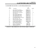
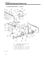
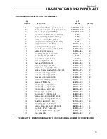
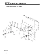
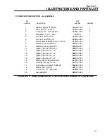
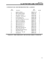
7.16 DUAL HOSE REEL OPTION -- ALL MODELS
key
part
number
description
number
quantity
1
support, hose reel manifold 110---250
02250048---573
1
2
support, hose reel 110---250 portables
02250048---574
1
3
hose, medium pressure 1”jic x 32”long
02250054---969
2
4
draw---bar, long pivot 185dpq
02250136---247
1
5
support, dr---bar swivel 185q
02250141---183
1
6
reel, hose 100ft 3/4”hose x 3/4”npt
040170
2
7
hose, assembly 5/8”id x 18”long
040885
2
8
valve, air velocity flow 3/4”npt
043480
2
9
adapter, swivel 90deg 3/4”h x 3/4”p
045241
2
10
support, service manifold
250002---145
1
11
oiler, 1qt microfog nogren
250005---016
1
12
u---bolt, hose reel mount 110---250
250008---322
2
13
valve, ball 3/4” service
250019---865
3
14
coupling, 3/4” male npt am7
250031---648
3
15
lubricator, cf 1 pt 1” 30cf
251315
1
16
oiler, line 2---quart 1” npt
405403
1
17
nut, hex f pltd 1/4---20
825304---236
4
18
nut, hex f pltd 5/16---18
825305---283
4
19
nut, hex locking 3/8---16
825506---198
12
20
capscrew, hex gr5 3/8---16 x 1
829106---100
8
21
screw, hex ser washer 5/16---18 x 3/4
829705---075
2
22
washer, pl---b reg pltd 1/4
838204---071
4
23
washer, pl---b reg pltd 5/16
838205---071
4
24
washer, pl---b reg pltd 3/8
838206---071
12
25
connector, 37 fl/mpt pltd 1 x 1
860116---100
1
26
elbow, 37fl 90m 1 x 1
860216---100
1
27
nipple, pipe---xs plt 3/4 x cl
866412---000
7
28
nipple, pipe---xs plt 1 x cl
866416---000
5
29
nipple, pipe---xs plt 1 x 2
866416---020
1
30
plug, pipe 1” 3000# stl plt
866900---040
1
31
elbow, pipe 90 deg 300# plt 3/4”
867030---030
2
32
bushing, red pltd 1 x 3/4
867104---030
3
33
coupling, pipe 1 300# plt
867430---040
1
34
cross, pipe 1” plt
867830---040
1
35
union, pipe---brs seat 1 300# plt
868030---040
1
36
u---bolt, 1/4” x 1” pipe pltd
868304---100
2
37
u---bolt, 5/16” x 1 1/4” pipe pltd
868305---125
1
38
tee, pipe pltd 1
868430---040
1
39
coupling, pipe 1 150# plt
869015---040
1
PLEASE NOTE: WHEN ORDERING PARTS, INDICATE SERIAL NUMBER OF COMPRESSOR
Summary of Contents for 185H
Page 6: ......
Page 14: ...8 NOTES...
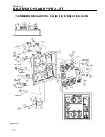
Page 20: ...Section 2 DESCRIPTION 14 Figure 2 4B Control System with Piping and Instrumentation 260 Models...
Page 23: ...Section 2 DESCRIPTION 17 Figure 2 6 Instrument Panel Group...
Page 24: ...Section 2 DESCRIPTION 18 Figure 2 7 Electrical System JOHN DEERE 02250144 446R05...
Page 25: ...Section 2 DESCRIPTION 19 Figure 2 7A Electrical System CATERPILLAR P02250144 395R04...
Page 26: ...20 NOTES...
Page 30: ...24 NOTES...
Page 36: ...Section 5 MAINTENANCE 30 Figure 5 4 Control System Adjustment 185H 210 MODELS 260 MODELS...
Page 42: ...36 NOTES...
Page 49: ...Section 7 ILLUSTRATIONS AND PARTS LIST 43 NOTES...
Page 90: ...Section 7 ILLUSTRATIONS AND PARTS LIST 84 7 10 ELECTRICAL PARTS ALL MODELS 02250148 897R00...
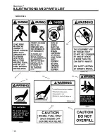
Page 128: ...Section 7 ILLUSTRATIONS AND PARTS LIST 122 7 20 DECALS...
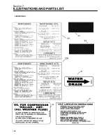
Page 130: ...Section 7 ILLUSTRATIONS AND PARTS LIST 124 7 20 DECALS...
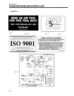
Page 132: ...Section 7 ILLUSTRATIONS AND PARTS LIST 126 7 20 DECALS...
Page 134: ...Section 7 ILLUSTRATIONS AND PARTS LIST 128 7 20 DECALS...
Page 136: ...Section 7 ILLUSTRATIONS AND PARTS LIST 130 7 20 DECALS...
Page 138: ...Section 7 ILLUSTRATIONS AND PARTS LIST 132 7 21 DECAL LOCATIONS 02250149 633R01...
Page 142: ......
Page 143: ......


