Section 3
SPECIFICATIONS
23
3.2 LUBRICATION GUIDE -- COMPRESSOR
FLUID TYPE
CHANGE PERIOD, HOURS
AMBIENT TEMPERATURE
RANGE
_
F (
_
C)
Sullair AWF
1200
---20 to 125 (---29 to 52)
D---A Torque Fluid
SAE10W SE, SF, SG, CD
MIL---L---2104E 10W
300
300
10 to 110 (---12 to 43)
0 to 100 (---18 to 38)
0 to 100 (---18 to 38)
300
(I)
(I)
Sullair part numbers for Sullair AWF are 250030---757 (5 gallons/20 liters) and 250030---758 (55 gallon drum/208 liters).
3.3 APPLICATION GUIDE
Sullair Air Compressors are supplied with Sullair
AWF which is heavy duty multi---viscosity, all---
weather fluid. Sullair AWF also allows an extended
change interval. Detergent motor oils (SAE 10W
Class SE,SF, SG or CD) can also be used. Any of
these oils are suitable under conditions where se-
vere oil oxidations can occur.
Water must be drained from the receiver periodical-
ly. In high ambient temperature and high humidity
conditions, condensed moisture may emulsify with
the oil forming a
“
milky” color. SAE 10W is especially
prone to this condition. The fluid should be changed
if this condition develops.
DO NOT
mix types of fluids. Combinations of differ-
ent fluids may lead to operational problems such as
foaming, filter plugging, orifice or line plugging.
When ambient conditions exceed those noted or if
conditions warrant use of other extended life lubri-
cants, contact Sullair for recommendations.
Sullair encourages the user to participate in a fluid
analysis program. This could result in a fluid change
interval differing from that stated in the manual. Sul-
lair Corporation offers a fluid analysis program for
Sullair AWF. Contact your local Sullair representa-
tive for details.
D---A Lubricant
r
Company Inc. offers an analysis
program for users of D---A products and Sullair AWF.
Contact your D---A lubricant supplier or Sullair rep-
resentative for details.
3.4 LUBRICATION GUIDE -- ENGINE
For engine oil specifications, refer to the Engine Op-
erator’s Manual.
Summary of Contents for 185H
Page 6: ......
Page 14: ...8 NOTES...
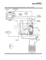
Page 20: ...Section 2 DESCRIPTION 14 Figure 2 4B Control System with Piping and Instrumentation 260 Models...
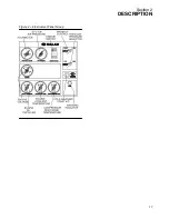
Page 23: ...Section 2 DESCRIPTION 17 Figure 2 6 Instrument Panel Group...
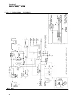
Page 24: ...Section 2 DESCRIPTION 18 Figure 2 7 Electrical System JOHN DEERE 02250144 446R05...
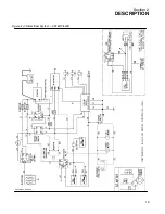
Page 25: ...Section 2 DESCRIPTION 19 Figure 2 7A Electrical System CATERPILLAR P02250144 395R04...
Page 26: ...20 NOTES...
Page 30: ...24 NOTES...
Page 36: ...Section 5 MAINTENANCE 30 Figure 5 4 Control System Adjustment 185H 210 MODELS 260 MODELS...
Page 42: ...36 NOTES...
Page 49: ...Section 7 ILLUSTRATIONS AND PARTS LIST 43 NOTES...
Page 90: ...Section 7 ILLUSTRATIONS AND PARTS LIST 84 7 10 ELECTRICAL PARTS ALL MODELS 02250148 897R00...
Page 128: ...Section 7 ILLUSTRATIONS AND PARTS LIST 122 7 20 DECALS...
Page 130: ...Section 7 ILLUSTRATIONS AND PARTS LIST 124 7 20 DECALS...
Page 132: ...Section 7 ILLUSTRATIONS AND PARTS LIST 126 7 20 DECALS...
Page 134: ...Section 7 ILLUSTRATIONS AND PARTS LIST 128 7 20 DECALS...
Page 136: ...Section 7 ILLUSTRATIONS AND PARTS LIST 130 7 20 DECALS...
Page 138: ...Section 7 ILLUSTRATIONS AND PARTS LIST 132 7 21 DECAL LOCATIONS 02250149 633R01...
Page 142: ......
Page 143: ......


