Section 4
OPERATION
25
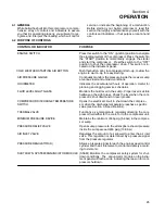
4.1 GENERAL
While Sullair has built into this compressor a compre-
hensive array of controls and indicators to assure
you that it is operating properly, you will want to rec-
ognize and interpret the reading which will call for
service or indicate the beginning of a malfunction.
Before starting your Sullair compressor, read this
section thoroughly and familiarize yourself with the
controls and indicators --- their purpose, location and
use.
4.2 PURPOSE OF CONTROLS
CONTROL OR INDICATOR
PURPOSE
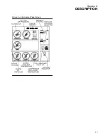
ENGINE SWITCH
Press this switch to the “ ON” (ignition) position to energize
the electrical system of the compressor. Press the switch to
the “START” position to momentarily engage the starter
and start the compressor. Pressthe switch to the “OFF”
position to shut the compressor down. This switch is lo-
cated on the instrument panel.
COLD WEATHER STARTING AID BUTTON
Push this button, prior to compressor start---up, to allow the
engine to warm---up for easy starting.
AIR PRESSURE GAUGE
Continually monitors the pressure inside the receiver sump
at various load and unload conditions.
HOURMETER
Indicates the accumulated hours of operation. Useful for
planning and logging service schedules.
FLUID LEVEL SIGHT GLASS
Monitors the fluid level in the sump. Proper level is visible
halfway up the sight glass. Check the level when the com-
pressor is shut down and on level ground.
COMPRESSOR DISCHARGE TEMPERATURE
Opens the electrical circuit to shut down the compres---
SWITCH
sor when the discharge temperature reaches a specific
value (see Section 3, Specifications).
THERMAL VALVE
Functions as a temperature regulator directing the com-
pressor fluid either to the cooler or to the compressor unit.
MINIMUM PRESSURE DEVICE
Maintains the minimum of 85 psig (5.9 bar) in the compres-
sor sump.
PRESSURE RELIEF VALVE
Opens sump pressure to the atmosphere should pressure
inside the sump exceed 200 psig (13.8 bar) .
AIR INLET VALVE
Regulates the amount of air allowed to enter the air inlet
valve. This regulation is determined by a pressure signal
from the pressure regulator.
PRESSURE REGULATOR (S)
Allows a pressure signal to reach the engine speed control
cylinder and the air inlet valve to control air delivery accord-
ing to demand.
SHUTDOWN SYSTEM/ANNUNCIATOR MODULE (SSAM) Monitors the compressor safety system for shut-
down conditions. The annunciator module on the instru-
ment panel will flash a code indicating the reason for com-
pressor shutdown.
Summary of Contents for 185H
Page 6: ......
Page 14: ...8 NOTES...
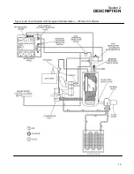
Page 20: ...Section 2 DESCRIPTION 14 Figure 2 4B Control System with Piping and Instrumentation 260 Models...
Page 23: ...Section 2 DESCRIPTION 17 Figure 2 6 Instrument Panel Group...
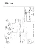
Page 24: ...Section 2 DESCRIPTION 18 Figure 2 7 Electrical System JOHN DEERE 02250144 446R05...
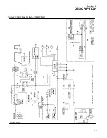
Page 25: ...Section 2 DESCRIPTION 19 Figure 2 7A Electrical System CATERPILLAR P02250144 395R04...
Page 26: ...20 NOTES...
Page 30: ...24 NOTES...
Page 36: ...Section 5 MAINTENANCE 30 Figure 5 4 Control System Adjustment 185H 210 MODELS 260 MODELS...
Page 42: ...36 NOTES...
Page 49: ...Section 7 ILLUSTRATIONS AND PARTS LIST 43 NOTES...
Page 90: ...Section 7 ILLUSTRATIONS AND PARTS LIST 84 7 10 ELECTRICAL PARTS ALL MODELS 02250148 897R00...
Page 128: ...Section 7 ILLUSTRATIONS AND PARTS LIST 122 7 20 DECALS...
Page 130: ...Section 7 ILLUSTRATIONS AND PARTS LIST 124 7 20 DECALS...
Page 132: ...Section 7 ILLUSTRATIONS AND PARTS LIST 126 7 20 DECALS...
Page 134: ...Section 7 ILLUSTRATIONS AND PARTS LIST 128 7 20 DECALS...
Page 136: ...Section 7 ILLUSTRATIONS AND PARTS LIST 130 7 20 DECALS...
Page 138: ...Section 7 ILLUSTRATIONS AND PARTS LIST 132 7 21 DECAL LOCATIONS 02250149 633R01...
Page 142: ......
Page 143: ......

