Section 4
OPERATION
26
4.2 PURPOSE OF CONTROLS (Continued)
CONTROL OR INDICATOR
PURPOSE
BLOWDOWN VALVE
Vents sump pressure to the atmosphere at shutdown.
IDLE WARM---UP CONTROL
Maintains a closed air inlet valve for reduced compressor
load on start---up. After engine starts, turn the handle of the
selector valve from the “start” to the “run” position for full
operation within the first minute of operation.
4.3 START--UP PROCEDURE
The following procedure should be used to make the
initial start---up of your compressor:
1. Position the compressor on a level surface so that
proper amounts of liquid can be added if neces-
sary.
(I)
2. Check oil and fluid levels both in the engine and
the cooling system(s). Maintain the proper level;
add if necessary.
3. Fill the fuel tank. Drain water from the fuel---water
separator.
4. Crack open one service line.
5. Bleed fuel injection lines if necessary (see Engine
Operator’s Manual).
6. Turn the warm---up control selector valve to the
start
position.
7. In cold weather, engage cold weather starting aid
button. Hold button for 5---10 seconds and then
release.
8. Press the engine switch to the
“ON”
position.
9. Press the engine switch to the
“START”
position
momentarily to engage starter, when engine
starts release switch.
10. After the engine starts, turn the idle warm---up se-
lector valve from
start
to
run
for full compressor
operation within the first 30 seconds of operation.
After 30 seconds, the annunciator light will go off.
11. Close canopy in order to maintain proper noise
control.
12. After the initial run, shut the compressor down and
refill the radiator and compressor fluid sump as re-
quired. Tighten any loose fittings and check fan
belt tension.
(I)
The radiator is filled with a 50/50 mixture of ethyl-
ene glycol and water. All engines receive Supple-
mental Coolant Additive (SCA) at the factory before
shipment. Refer to your Engine Operator’s Manual
for details and specific engine requirements.
4.4 SUBSEQUENT START--UP PROCEDURE
On subsequent starts, follow the procedure ex-
plained below:
1. Check engine oil, water and fuel levels.
2. Check compressor fluid level (should be visible in
sight glass). Drain water from the fuel---water
separator.
3. Check dust collectors and clean if necessary.
4. Crack open service valve.
5. Bleed fuel injection lines if necessary (see Engine
Operator’s Manual).
6. Turn the warm---up control selector valve to the
start
position.
7. In cold weather, engage cold weather starting aid
button. Hold button for 5---10 seconds and then
release.
8. Press the engine switch to the
“ON”
position.
9. Press the engine switch to the
“START”
position
momentarily to engage starter, when engine
starts release switch.
10. Allow for sufficient warm up of compressor before
operating.
11. After the engine starts, turn the idle warm---up se-
lector valve from the
start
to
run
position for full
operation within the first 30 seconds of operation.
4.5 SHUTDOWN PROCEDURE
To shut the compressor down, close the service
valves and run compressor for approximately 5 min-
utes to allow the compressor to cool down and
press the engine switch to the
OFF
position. In
case of emergency where immediate shutdown is
required, this procedure is not necessary. The en-
gine switch should be pressed to the
OFF
position
immediately.
Summary of Contents for 185H
Page 6: ......
Page 14: ...8 NOTES...
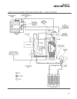
Page 20: ...Section 2 DESCRIPTION 14 Figure 2 4B Control System with Piping and Instrumentation 260 Models...
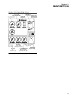
Page 23: ...Section 2 DESCRIPTION 17 Figure 2 6 Instrument Panel Group...
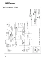
Page 24: ...Section 2 DESCRIPTION 18 Figure 2 7 Electrical System JOHN DEERE 02250144 446R05...
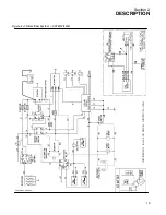
Page 25: ...Section 2 DESCRIPTION 19 Figure 2 7A Electrical System CATERPILLAR P02250144 395R04...
Page 26: ...20 NOTES...
Page 30: ...24 NOTES...
Page 36: ...Section 5 MAINTENANCE 30 Figure 5 4 Control System Adjustment 185H 210 MODELS 260 MODELS...
Page 42: ...36 NOTES...
Page 49: ...Section 7 ILLUSTRATIONS AND PARTS LIST 43 NOTES...
Page 90: ...Section 7 ILLUSTRATIONS AND PARTS LIST 84 7 10 ELECTRICAL PARTS ALL MODELS 02250148 897R00...
Page 128: ...Section 7 ILLUSTRATIONS AND PARTS LIST 122 7 20 DECALS...
Page 130: ...Section 7 ILLUSTRATIONS AND PARTS LIST 124 7 20 DECALS...
Page 132: ...Section 7 ILLUSTRATIONS AND PARTS LIST 126 7 20 DECALS...
Page 134: ...Section 7 ILLUSTRATIONS AND PARTS LIST 128 7 20 DECALS...
Page 136: ...Section 7 ILLUSTRATIONS AND PARTS LIST 130 7 20 DECALS...
Page 138: ...Section 7 ILLUSTRATIONS AND PARTS LIST 132 7 21 DECAL LOCATIONS 02250149 633R01...
Page 142: ......
Page 143: ......


