Section 5
MAINTENANCE
27
5.1 GENERAL
A good maintenance program is the key to long
compressor life. Below is a program that, when ad-
hered to, should keep the compressor in top operat-
ing condition. For maintenance requirements on en-
gine, refer to the Engine Operator’s Manual for a de-
tailed description of service instructions. See Sec-
tion 5.7, Parts Replacement and Adjustment Proce-
dures for a detailed description of specific compres-
sor system components. Prior to performing main-
tenance, read the CIMA Safety Manual, if applicable
in your area.
WARNING
!
DO NOT remove caps, plugs and/or other compo-
nents when compressor is running or pressur-
ized.
Stop compressor and relieve all internal pressure
before doing so.
5.2 DAILY OPERATION
Prior to starting the compressor, it is necessary to
check the fluid level in the sump. Should the level be
low, simply add the necessary amount. If the addi-
tion of fluid becomes too frequent, a simple problem
has developed which is causing this excessive loss.
See the Troubleshooting Sections (
and
) un-
der Excessive Fluid Consumption for a probable
cause and remedy. Also check the engine oil level
and the radiator coolant level and drain water from
the engine fuel/water separator prior to starting.
NOTE
The radiator and engine cooling system must be
drained and flushed every two (2) years. Replace
the coolant with a solution of 50% ethylene glycol
and 50% water or as required for your geographic
location. DO NOT use a leak sealing type of anti---
freeze. All engines must have Supplemental Cool-
ant Additive (SCA) added to the engine coolant
system. Refer to your Engine Operator’s Manual
for details and specific engine requirements.
After a routine start has been made, observe the in-
strument panel gauge and be sure it monitors the
correct reading for that particular phase of opera-
tion. After the compressor has warmed up, it is rec-
ommended that a general check on the overall com-
pressor and instrument panel be made to assure
that the compressor is running properly. Also check
the air filter maintenance indicators if supplied.
5.3 MAINTENANCE AFTER INITIAL 50 HOURS
OF OPERATION
After the initial 50 hours of operation, a few mainte-
nance requirements are needed to rid the system of
any foreign materials. Perform the following mainte-
nance operations to prevent unnecessary prob-
lems.
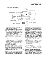
1. Clean the return line orifice and strainer.
2. Change compressor fluid filter.
3. Check Engine Operator’s Manual for required
service.
4. Check fuel filter for water.
5.3A MAINTENANCE EVERY 50 HOURS
1. Inspect and replace air filter elements (if re-
quired).
2. Check fuel filter for water.
5.4 MAINTENANCE EVERY 100 HOURS
After 100 hours of operation, it will be necessary to
perform the following:
1. Clean the radiator and cooler exteriors.
2. Check Engine Operator’s Manual for required
service.
5.5 MAINTENANCE EVERY 250 HOURS
Perform the following after every 250 hours of opera-
tion:
1. Check fan belt tension.
2. Clean the radiator and cooler exterior. Depending
on how contaminated the atmosphere may be,
more frequent cooler and radiator cleaning may
be necessary.
3. Change engine oil and filter.
NOTE
Fluid change period will vary according to fluid
brand. Refer to Lubrication Guide in Section 3.
Perform the following after every 250 hours of opera-
tion:
4. Change the compressor fluid and fluid filter, if not
using Sullair AWF. Run the compressor for 5 to
10 minutes to warm the fluid. Shut the compres-
sor off and relieve all internal pressure before
proceeding. Drain the fluid sump by removing
the plug at the bottom of the sump tank. For fluid
filter element replacement, see Filter Element
Replacement under the Maintenance Section
5.7 Parts Replacement and Adjustment Proce-
dures. Fill the sump with fluid according to speci-
fications in Section 3. Remove any accumulated
dirt from the fluid filler cap prior to filling the
sump.
5. Replace return line strainer.
6. Check the engine RPM. Idle speeds should never
be allowed to fall below the minimums (see Sec-
tion 3 Specifications).
7. Change the fuel filter . Should persistant clogging
be evident, change the fuel filter more frequently.
8. Change engine fuel---water separator.
9. Change the air filter (s) primary elements.
10.Change compressor fuild filter.
NOTE
Operation at speeds below the minimum idle
speeds shown in the Table in Section 3, Specifica-
tions will damage the compressor. Extended op-
eration below those speeds will induce coupling
and/or compressor failures.
11. Lubricate the control linkage.
12. Check Engine Manual for required service.
Summary of Contents for 185H
Page 6: ......
Page 14: ...8 NOTES...
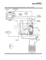
Page 20: ...Section 2 DESCRIPTION 14 Figure 2 4B Control System with Piping and Instrumentation 260 Models...
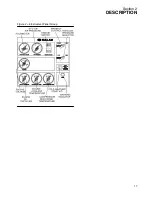
Page 23: ...Section 2 DESCRIPTION 17 Figure 2 6 Instrument Panel Group...
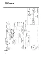
Page 24: ...Section 2 DESCRIPTION 18 Figure 2 7 Electrical System JOHN DEERE 02250144 446R05...
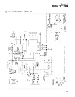
Page 25: ...Section 2 DESCRIPTION 19 Figure 2 7A Electrical System CATERPILLAR P02250144 395R04...
Page 26: ...20 NOTES...
Page 30: ...24 NOTES...
Page 36: ...Section 5 MAINTENANCE 30 Figure 5 4 Control System Adjustment 185H 210 MODELS 260 MODELS...
Page 42: ...36 NOTES...
Page 49: ...Section 7 ILLUSTRATIONS AND PARTS LIST 43 NOTES...
Page 90: ...Section 7 ILLUSTRATIONS AND PARTS LIST 84 7 10 ELECTRICAL PARTS ALL MODELS 02250148 897R00...
Page 128: ...Section 7 ILLUSTRATIONS AND PARTS LIST 122 7 20 DECALS...
Page 130: ...Section 7 ILLUSTRATIONS AND PARTS LIST 124 7 20 DECALS...
Page 132: ...Section 7 ILLUSTRATIONS AND PARTS LIST 126 7 20 DECALS...
Page 134: ...Section 7 ILLUSTRATIONS AND PARTS LIST 128 7 20 DECALS...
Page 136: ...Section 7 ILLUSTRATIONS AND PARTS LIST 130 7 20 DECALS...
Page 138: ...Section 7 ILLUSTRATIONS AND PARTS LIST 132 7 21 DECAL LOCATIONS 02250149 633R01...
Page 142: ......
Page 143: ......

