Section 7
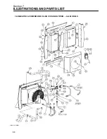
ILLUSTRATIONS AND PARTS LIST
51
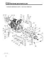
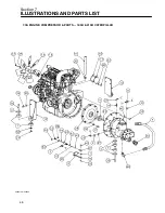
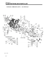
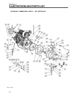
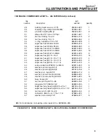
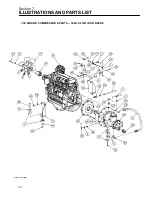
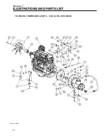
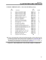
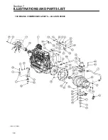
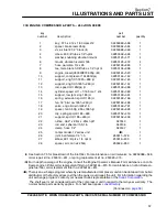
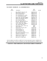
7.3B ENGINE, COMPRESSOR & PARTS -- 260 CATERPILLAR (continued)
key
part
number
description
number
quantity
28
bushing, taper wood---sd 1.75
250034---920
1
29
coupling, eng---compr lord 250
(III)
250034---921
1
30
pin,drive coupling 250 jd
250035---041
8
31
elbow, 90d 1/4” tube x 1/4”fnpt
250041---287
1
32
nut, hex locking 1/4---20
825504---145
2
33
nut, hex locking 1/2---13
825508---262
4
34
o---ring, neoprene 3 1/2 x 1/8”
826202---238
1
35
capscrew, hex 8.8 m6 x 16mm
828006---016
1
36
capscrew, hex 8.8 m8 x 65mm
828008---065
4
37
capscrew, hex 8.8 m10 x 25mm
828010---025
2
38
capscrew, hex 8.8 m10 x 35mm
828010---035
12
39
capscrew, hex 8.8 m12 x 25mm
828012---025
8
40
capscrew, hex gr5 1/2---13 x 1
829108---100
14
41
capscrew, hex gr5 1/2---13 x 1 1/4
829108---125
4
42
capscrew, hex gr5 1/2---13 x 3 1/4
829108---325
4
43
capscrew, hex gr5 5/8---11 x 1 1/4
829110---125
4
44
screw, socket iso 4762 m10 x 40mm
829310---040
8
45
washer, spr lock reg pltd 1/2
837808---125
8
46
washer, spr lock reg pltd 5/8
837810---156
4
47
washer, pl---b reg pltd 1/2
838208---112
4
48
washer, spr lock---metric pltd m8
838808---200
4
49
washer, spr lock---metric pltd m10
838810---220
14
50
hose, heater 3/4
842115---075
1 ft
51
nut, hex jam lh pltd 1/4---28
866604---164
1
52
plug, pipe 1/8” 3000# stl plt
866900---005
1
53
capscrew, ferry head hd pltd 1/4---20 x 1
867304---100
1
54
capscrew, ferry head hd pltd 1/4---20 x 1 1/2
867304---150
1
55
nut, hex jam rh pltd 1/4---28
868204---164
2
56
connector, 90d str x jic 1 7/8 x 1 7/8
870624---024
1
57
washer, nord---lock pl 1/2”
878608---077
8
(III)
For maintenance on coupling, order repair kit no. 02250099---930.
PLEASE NOTE: WHEN ORDERING PARTS, INDICATE SERIAL NUMBER OF COMPRESSOR
Summary of Contents for 185H
Page 6: ......
Page 14: ...8 NOTES...
Page 20: ...Section 2 DESCRIPTION 14 Figure 2 4B Control System with Piping and Instrumentation 260 Models...
Page 23: ...Section 2 DESCRIPTION 17 Figure 2 6 Instrument Panel Group...
Page 24: ...Section 2 DESCRIPTION 18 Figure 2 7 Electrical System JOHN DEERE 02250144 446R05...
Page 25: ...Section 2 DESCRIPTION 19 Figure 2 7A Electrical System CATERPILLAR P02250144 395R04...
Page 26: ...20 NOTES...
Page 30: ...24 NOTES...
Page 36: ...Section 5 MAINTENANCE 30 Figure 5 4 Control System Adjustment 185H 210 MODELS 260 MODELS...
Page 42: ...36 NOTES...
Page 49: ...Section 7 ILLUSTRATIONS AND PARTS LIST 43 NOTES...
Page 90: ...Section 7 ILLUSTRATIONS AND PARTS LIST 84 7 10 ELECTRICAL PARTS ALL MODELS 02250148 897R00...
Page 128: ...Section 7 ILLUSTRATIONS AND PARTS LIST 122 7 20 DECALS...
Page 130: ...Section 7 ILLUSTRATIONS AND PARTS LIST 124 7 20 DECALS...
Page 132: ...Section 7 ILLUSTRATIONS AND PARTS LIST 126 7 20 DECALS...
Page 134: ...Section 7 ILLUSTRATIONS AND PARTS LIST 128 7 20 DECALS...
Page 136: ...Section 7 ILLUSTRATIONS AND PARTS LIST 130 7 20 DECALS...
Page 138: ...Section 7 ILLUSTRATIONS AND PARTS LIST 132 7 21 DECAL LOCATIONS 02250149 633R01...
Page 142: ......
Page 143: ......

