Section 5
MAINTENANCE
28
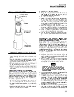
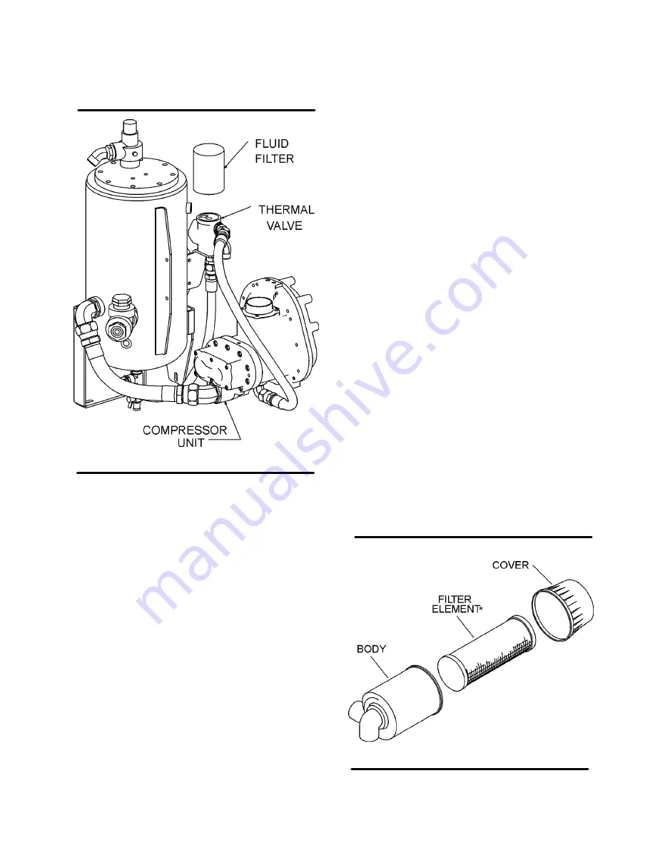
Figure 5---1 Compressor Fluid Filter
* Replacement Element Kit P/N 250028---032
13. Clean the return line orifice.
5.6A MAINTENANCE EVERY 1500 HOURS OR
ANNUALLY
1. When using Sullair AWF, change the compressor
fluid and replace the fluid filter element (See
maintenance procedures in Section 5.7).
2. Service engine cooling system.
5.6B MAINTENANCE EVERY YEAR OR 12,000
MILES
1. Lubricate axle bearings on wheel---mounted
units.
5.7 PARTS REPLACEMENT AND ADJUSTMENT
PROCEDURES
COMPRESSOR FLUID CHANGE PROCEDURE
Warm---up compressor for 5 to 10 minutes to warm
the fluid. Shut the compressor off and relieve all in-
ternal pressure before proceeding. Drain the fluid
sump by opening the valve at the bottom of the
sump tank. Change the compressor fluid and re-
place the fluid filter element. For element replace-
ment see procedure for servicing the fluid filter in
this section. Fill the sump with fluid according to
specifications in Section 3.
COMPRESSOR FLUID FILTER ELEMENT RE-
PLACEMENT
Refer to Figure
.
1. Using a strap wrench, remove the old element.
2. Clean the gasket seating surface.
3. Apply a light film of fluid to the new gasket.
4. Hand tighten the new element (from kit P/N
250028---032) until the new gasket is seated on
the gasket seat.
5. Continue tightening the element by hand an addi-
tional 1/2 to 3/4 turn.
6. Restart the compressor and check for leaks.
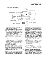
AIR FILTER MAINTENANCE
Refer to Figure
. Air filter maintenance should
be performed as often as conditions require. If the
filters are equipped with an optional maintenance
indicator, maintenance should be done when the in-
dicator shows red. The following procedure will ex-
plain how to replace the air filter element.
AIR FILTER ELEMENT REPLACEMENT
1. Loosen and remove the air filter end cover.
2. Remove element.
3. Clean the body and cover with a damp cloth in-
side and out.
4. Replace the new filter element.
5. Reposition the cover and lock into position.
6. Reset the air filter restriction indicator if so
equipped, and the unit will be ready for opera-
tion.
ELEMENT INSPECTION
1. Place a bright light inside the element to inspect
for damage or leak holes. Concentrated light will
Figure 5---2 Air Filter
*Filter Element P/N 02250122---816 (2 req’d)
Summary of Contents for 185H
Page 6: ......
Page 14: ...8 NOTES...
Page 20: ...Section 2 DESCRIPTION 14 Figure 2 4B Control System with Piping and Instrumentation 260 Models...
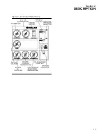
Page 23: ...Section 2 DESCRIPTION 17 Figure 2 6 Instrument Panel Group...
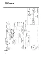
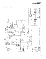
Page 24: ...Section 2 DESCRIPTION 18 Figure 2 7 Electrical System JOHN DEERE 02250144 446R05...
Page 25: ...Section 2 DESCRIPTION 19 Figure 2 7A Electrical System CATERPILLAR P02250144 395R04...
Page 26: ...20 NOTES...
Page 30: ...24 NOTES...
Page 36: ...Section 5 MAINTENANCE 30 Figure 5 4 Control System Adjustment 185H 210 MODELS 260 MODELS...
Page 42: ...36 NOTES...
Page 49: ...Section 7 ILLUSTRATIONS AND PARTS LIST 43 NOTES...
Page 90: ...Section 7 ILLUSTRATIONS AND PARTS LIST 84 7 10 ELECTRICAL PARTS ALL MODELS 02250148 897R00...
Page 128: ...Section 7 ILLUSTRATIONS AND PARTS LIST 122 7 20 DECALS...
Page 130: ...Section 7 ILLUSTRATIONS AND PARTS LIST 124 7 20 DECALS...
Page 132: ...Section 7 ILLUSTRATIONS AND PARTS LIST 126 7 20 DECALS...
Page 134: ...Section 7 ILLUSTRATIONS AND PARTS LIST 128 7 20 DECALS...
Page 136: ...Section 7 ILLUSTRATIONS AND PARTS LIST 130 7 20 DECALS...
Page 138: ...Section 7 ILLUSTRATIONS AND PARTS LIST 132 7 21 DECAL LOCATIONS 02250149 633R01...
Page 142: ......
Page 143: ......


