Section 5
MAINTENANCE
31
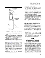
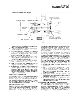
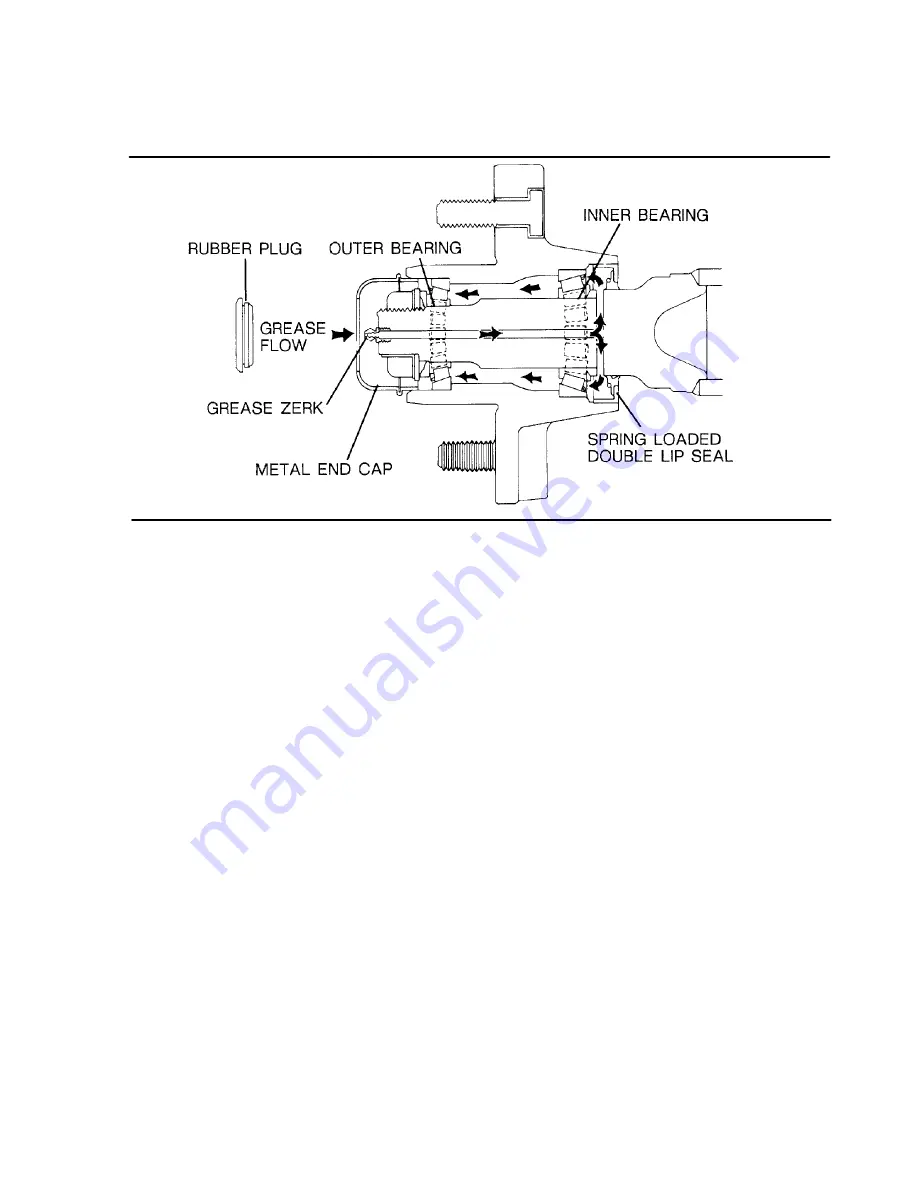
Figure 5---5 Typical E---Z Lube Axle
valve and allow the compressor to cycle and re-
check low engine speed (idle).
The following explanation applies to “H” compres-
sor with dual pressure controls.
1. Start the compressor and allow the engine to
warm---up to normal operating temperature with
the service valve closed and the pressure selec-
tor switch set to the “low” position.
2. Follow the procedure for setting the controls at
100 psig (6.9 bar) rated full load pressure as de-
scribed in Steps 2 through 5 above.
3. Switch the pressure selector switch to the “high”
position with the service valve closed.
4. Adjust the high pressure regulator so that the
compressor maintains 165 psig (11.4 bar).
5. Gradually open the service valve to atmosphere
until the engine comes up in speed and sump
pressure is held at 150 psig (10.3 bar). At this
point the engine should be at rated speed. If nec-
essary, to raise or lower the speed, lengthen or
shorten the rod respectively.
OPERATING ADJUSTMENTS
The first step is to start the compressor according to
the instructions in Section 4, Subsequent Start---up.
Allow the engine to operate until it reaches the nor-
mal operating temperature. Open the service valve
until the engine speed increases to, or close to, the
maximum specified operating speed.
BEARING LUBRICATION
Refer to Figure
. Proper lubrication is essential
to the proper functioning and reliability of your por-
table compressor axle. Wheel bearings should be
lubricated at least once every 12 months, or more
frequently to help insure proper performance. Use
wheel bearing grease that conforms to military
specification MIL---G---10924 or a high temperature
wheel bearing grease such as lithium complex NLGI
Consistency #2.
If your axle is equipped with the E---Z Lube feature,
the bearings can be periodically lubricated without
removing the hubs from the axle. This feature con-
sists of axle spindles that have been specially drilled
and fitted with a grease zerk in their ends. When
grease is pumped into the zerk, it is channeled to
the inner bearing and then flows back to the outer
bearing and eventually back out of the grease cap
hold (see Figure
). The procedure is as follows:
1. Remove the rubber plug from the end of the
grease cap.
2. With a standard grease gun filled with a quality
wheel bearing grease, place the gun onto the
grease zerk located in the end of the spindle.
Make sure the grease gun nozzle is fully en-
gaged on the fitting.
3. Pump grease into the zerk. The old, displaced
grease will begin to flow back out the cap around
the grease gun nozzle.
4. When the new, clean grease is observed, remove
the grease gun, wipe off any excess, and replace
the rubber plug in the cap.
5.8 TROUBLESHOOTING -- INTRODUCTION
The following Troubleshooting Chart is based upon
the data obtained both from testing at the factory
and from applied situations in the field. It contains
symptoms and usual causes for the described
problems, however
DO NOT
assume that these are
the only problems that may occur. All available data
Summary of Contents for 185H
Page 6: ......
Page 14: ...8 NOTES...
Page 20: ...Section 2 DESCRIPTION 14 Figure 2 4B Control System with Piping and Instrumentation 260 Models...
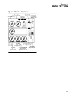
Page 23: ...Section 2 DESCRIPTION 17 Figure 2 6 Instrument Panel Group...
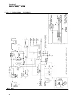
Page 24: ...Section 2 DESCRIPTION 18 Figure 2 7 Electrical System JOHN DEERE 02250144 446R05...
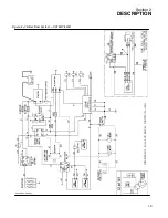
Page 25: ...Section 2 DESCRIPTION 19 Figure 2 7A Electrical System CATERPILLAR P02250144 395R04...
Page 26: ...20 NOTES...
Page 30: ...24 NOTES...
Page 36: ...Section 5 MAINTENANCE 30 Figure 5 4 Control System Adjustment 185H 210 MODELS 260 MODELS...
Page 42: ...36 NOTES...
Page 49: ...Section 7 ILLUSTRATIONS AND PARTS LIST 43 NOTES...
Page 90: ...Section 7 ILLUSTRATIONS AND PARTS LIST 84 7 10 ELECTRICAL PARTS ALL MODELS 02250148 897R00...
Page 128: ...Section 7 ILLUSTRATIONS AND PARTS LIST 122 7 20 DECALS...
Page 130: ...Section 7 ILLUSTRATIONS AND PARTS LIST 124 7 20 DECALS...
Page 132: ...Section 7 ILLUSTRATIONS AND PARTS LIST 126 7 20 DECALS...
Page 134: ...Section 7 ILLUSTRATIONS AND PARTS LIST 128 7 20 DECALS...
Page 136: ...Section 7 ILLUSTRATIONS AND PARTS LIST 130 7 20 DECALS...
Page 138: ...Section 7 ILLUSTRATIONS AND PARTS LIST 132 7 21 DECAL LOCATIONS 02250149 633R01...
Page 142: ......
Page 143: ......

