Section 7
ILLUSTRATIONS AND PARTS LIST
55
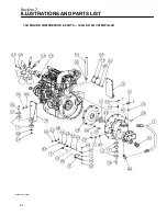
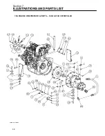
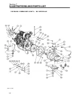
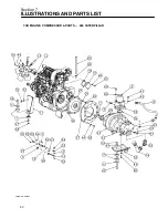
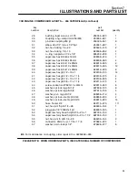
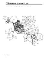
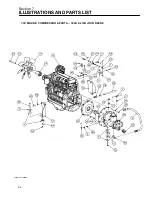
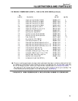
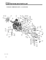
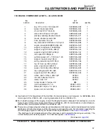
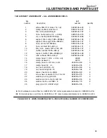
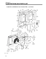
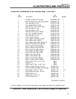
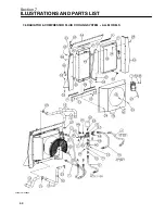
7.3C ENGINE, COMPRESSOR & PARTS -- 185H & 210H JOHN DEERE (continued)
key
part
number
description
number
quantity
34
capscrew, hex 8.8 m8 x 120mm
828008---120
4
35
capscrew, hex 8.8 m10 x 35mm
828010---035
12
36
capscrew, hex 8.8 m12 x 75mm
828012---075
2
37
capscrew, hex 8.8 m16 x 30mm
828016---030
4
38
capscrew, hex gr5 1/4---20 x 1
829104---100
1
39
capscrew, hex gr5 1/2---13 x 3 1/4
829108---325
2
40
washer, pl---b reg pltd 5/16
838205---071
3
41
washer, pl---b reg pltd 1/2
838208---112
2
42
washer, spr lock---metric pltd m8
838808---200
6
43
washer, spr lock---metric pltd m10
838810---220
12
44
hose, heater 5/8
842115---062
1 ft
45
key, paral iso r773 10x8x40
865210---040
1
46
nut, hex jam lh pltd 1/4---28
866604---164
1
47
capscrew, ferry head hd pltd 1/4---20 x 1
867304---100
1
48
capscrew, ferry head hd pltd 1/4---20 x 1 1/2
867304---150
1
49
capscrew, ferry head hd pltd 3/8---16 x 1 1/2
867306---150
8
50
nut, hex jam rh pltd 1/4---28
868204---164
1
51
nut, hex jam rh pltd 5/16---24
868205---195
1
52
connector, 45 deg str x jic 1 7/8 x 1 7/8
870524---024
1
53
connector, 90d str x jic 1 1/16 x 1 1/16
870612---012
1
54
adapter, pipe male 7/16 orng x 1/8
877202---012
1
55
washer, nord---lock pl 5/8”
878610---100
4
56
compressor & part, dxx102147e
(III)
1
(III)
There is an exchange program whereby a remanufactured compressor unit can be obtained from Sull-
air distributors or the factory at less cost than the owner could repair the unit. For information regarding
the unit exchange program, contact your nearest Sullair representative or the
The shaft seal is not considered part of the compressor unit in regard to the two year warranty. The
normal Sullair parts warranty applies. For shaft seal repairs
PLEASE NOTE: WHEN ORDERING PARTS, INDICATE SERIAL NUMBER OF COMPRESSOR
Summary of Contents for 185H
Page 6: ......
Page 14: ...8 NOTES...
Page 20: ...Section 2 DESCRIPTION 14 Figure 2 4B Control System with Piping and Instrumentation 260 Models...
Page 23: ...Section 2 DESCRIPTION 17 Figure 2 6 Instrument Panel Group...
Page 24: ...Section 2 DESCRIPTION 18 Figure 2 7 Electrical System JOHN DEERE 02250144 446R05...
Page 25: ...Section 2 DESCRIPTION 19 Figure 2 7A Electrical System CATERPILLAR P02250144 395R04...
Page 26: ...20 NOTES...
Page 30: ...24 NOTES...
Page 36: ...Section 5 MAINTENANCE 30 Figure 5 4 Control System Adjustment 185H 210 MODELS 260 MODELS...
Page 42: ...36 NOTES...
Page 49: ...Section 7 ILLUSTRATIONS AND PARTS LIST 43 NOTES...
Page 90: ...Section 7 ILLUSTRATIONS AND PARTS LIST 84 7 10 ELECTRICAL PARTS ALL MODELS 02250148 897R00...
Page 128: ...Section 7 ILLUSTRATIONS AND PARTS LIST 122 7 20 DECALS...
Page 130: ...Section 7 ILLUSTRATIONS AND PARTS LIST 124 7 20 DECALS...
Page 132: ...Section 7 ILLUSTRATIONS AND PARTS LIST 126 7 20 DECALS...
Page 134: ...Section 7 ILLUSTRATIONS AND PARTS LIST 128 7 20 DECALS...
Page 136: ...Section 7 ILLUSTRATIONS AND PARTS LIST 130 7 20 DECALS...
Page 138: ...Section 7 ILLUSTRATIONS AND PARTS LIST 132 7 21 DECAL LOCATIONS 02250149 633R01...
Page 142: ......
Page 143: ......

