Section 6
MAINTENANCE
27
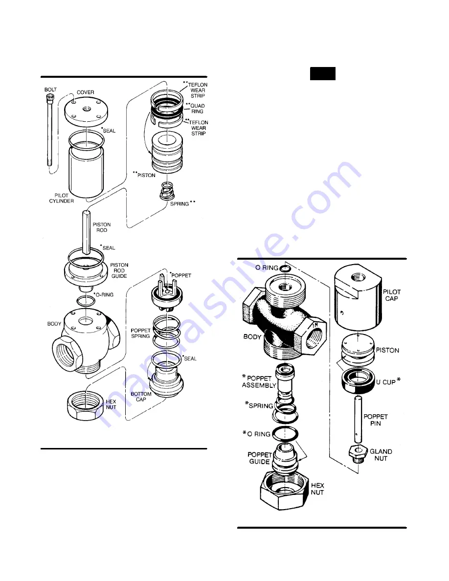
Figure 6-9 Fluid Stop Valve (P/N 250038-489)
*Repair Kit P/N 250038-494 (o-rings & poppet)
**Repair Kit P/N 250038-490 (piston & parts)
14. Install piston rod guide with new o--ring installed.
15. Install piston rod if provided.
16. Install the spring onto the piston rod guide with
large side down.
17. Install the quad ring and the two (2) Teflon rings
onto the piston. Coat the quad ring with Parker
Super “O” ring seal or equivalent quality silicone
grease.
18. Install the piston into the pilot cylinder.
NOTE
Cylinder is chamfered on one end. Install from this
side.
19. Install the two (2) seals; one into the cover and the
other onto the piston rod guide.
20. Place cylinder over pilot guide.
21. Replace the cover and the four (4) nuts onto the
cover. Tighten nuts alternately at opposite sides
of the cover in a crisscross patter. Check to see
that cylinder is seated on seals on both ends.
RUNNING BLOWDOWN VALVE MAINTENANCE
. W hen it is nec es s ar y t o r epair
the running blowdown valve (P/N 045116), use re-
pair kit no. 047524, and follow the instructions pro-
vided below.
1. Remove the hex nut from the bottom of the valve.
The poppet guide which is secured by the hex nut
is under slight spring tension.
2. Remove the poppet guide, poppet assembly and
spring from the valve body.
* Repair Kit P/N 047524
(P/N 045116)
Figure 6-10 Running Blowdown Valve
Summary of Contents for 20/12 500 CFM
Page 12: ...Section 2 DESCRIPTION 8 Figure 2 3 Piping and Instrumentation...
Page 14: ...Section 2 DESCRIPTION 10 Figure 2 5 Capacity Control System Typical...
Page 18: ...14 NOTES...
Page 20: ...16 NOTES...
Page 24: ...20 NOTES...
Page 38: ...34 NOTES...
Page 40: ...Section 7 ILLUSTRATIONS AND PARTS LIST 36 7 3 MOTOR FRAME COMPRESSOR AND PARTS...
Page 42: ...Section 7 ILLUSTRATIONS AND PARTS LIST 38 7 4 AIR INLET SYSTEM...
Page 44: ...Section 7 ILLUSTRATIONS AND PARTS LIST 40 7 5 COOLING AND LUBRICATION SYSTEM...
Page 46: ...Section 7 ILLUSTRATIONS AND PARTS LIST 42 7 6 COOLER ASSEMBLY...
Page 48: ...Section 7 ILLUSTRATIONS AND PARTS LIST 44 7 7 DISCHARGE SYSTEM...
Page 50: ...Section 7 ILLUSTRATIONS AND PARTS LIST 46 7 7 DISCHARGE SYSTEM...
Page 52: ...Section 7 ILLUSTRATIONS AND PARTS LIST 48 7 8 INSTRUMENT PANEL AND PARTS...
Page 54: ...Section 7 ILLUSTRATIONS AND PARTS LIST 50 7 9 CONTROL SYSTEM...
Page 56: ...Section 7 ILLUSTRATIONS AND PARTS LIST 52 7 9 CONTROL SYSTEM...
Page 58: ...Section 7 ILLUSTRATIONS AND PARTS LIST 54 7 10 ELECTRIC CONTROL BOX...
Page 60: ...Section 7 ILLUSTRATIONS AND PARTS LIST 56 7 11 UNIT TUBING...
Page 62: ...Section 7 ILLUSTRATIONS AND PARTS LIST 58 7 11 UNIT TUBING...
Page 64: ...Section 7 ILLUSTRATIONS AND PARTS LIST 60 7 12 DECAL GROUP...


