Section 2
DESCRIPTION
5
2.1 INTRODUCTION
Your new Sullair electric 2--stage motor driven air
compressor offers superior performance and reli-
ability requiring a minimal amount of maintenance.
Your compressor is equipped with a 2--stage Sullair
rotary screw air compressor. Compared to other
compressors, the Sullair is unique in mechanical
reliability, with virtually no wear or loss of perfor-
mance. With a Sullair compressor, there is no in-
spection required of the working parts within the
compressor unit.
As you will see in the following pages, it is very easy
to care for, and/or, to maintain a Sullair compressor.
By careful and step--by--step adherence to the
guidelines and procedure, operator(s) will be able to
keep the compressor in top operational condition.
2.2 DESCRIPTION OF COMPONENTS
. T he c om ponent s of t he S ullair
2--stage electric compressor include
compressor
unit
,
electric motor
,
cooling and lubrication
system
,
air inlet system
,
compressor discharge
system
,
capacity control system
and
instrument
panel
.
The 2--stage Sullair compressor unit is driven by an
industrial motor designed to provide enough horse-
power for more than adequate reserve at rated con-
ditions.
On air--cooled models, a separate motor driven fan
forces air through the cooler, thereby removing the
compression heat from the cooling fluid.
Provisions are made for easy access to such com-
ponents as the fluid filters, control valves and the air
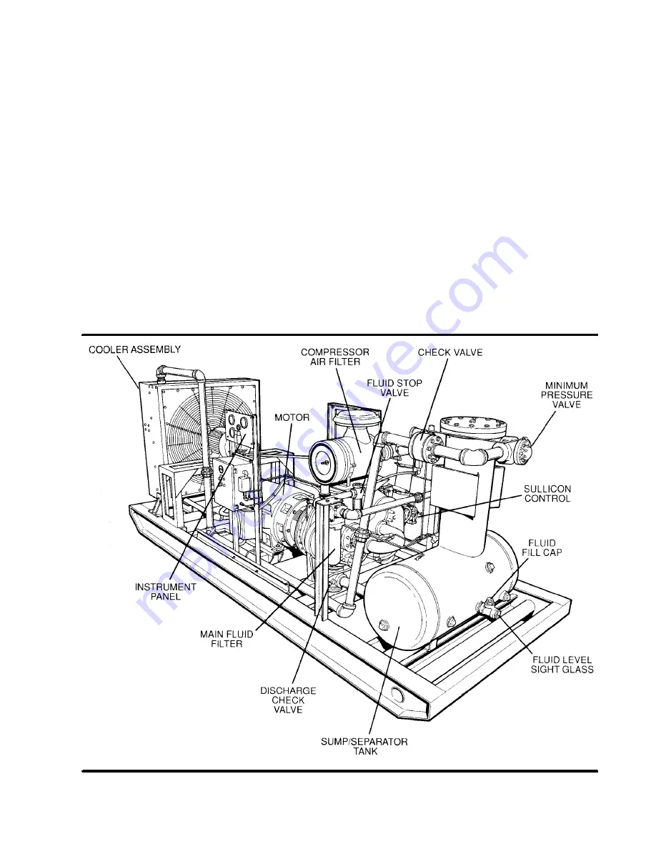
Figure 2-1 Sullair 20/12 Rotary Screw Air Compressor
Summary of Contents for 20/12 500 CFM
Page 12: ...Section 2 DESCRIPTION 8 Figure 2 3 Piping and Instrumentation...
Page 14: ...Section 2 DESCRIPTION 10 Figure 2 5 Capacity Control System Typical...
Page 18: ...14 NOTES...
Page 20: ...16 NOTES...
Page 24: ...20 NOTES...
Page 38: ...34 NOTES...
Page 40: ...Section 7 ILLUSTRATIONS AND PARTS LIST 36 7 3 MOTOR FRAME COMPRESSOR AND PARTS...
Page 42: ...Section 7 ILLUSTRATIONS AND PARTS LIST 38 7 4 AIR INLET SYSTEM...
Page 44: ...Section 7 ILLUSTRATIONS AND PARTS LIST 40 7 5 COOLING AND LUBRICATION SYSTEM...
Page 46: ...Section 7 ILLUSTRATIONS AND PARTS LIST 42 7 6 COOLER ASSEMBLY...
Page 48: ...Section 7 ILLUSTRATIONS AND PARTS LIST 44 7 7 DISCHARGE SYSTEM...
Page 50: ...Section 7 ILLUSTRATIONS AND PARTS LIST 46 7 7 DISCHARGE SYSTEM...
Page 52: ...Section 7 ILLUSTRATIONS AND PARTS LIST 48 7 8 INSTRUMENT PANEL AND PARTS...
Page 54: ...Section 7 ILLUSTRATIONS AND PARTS LIST 50 7 9 CONTROL SYSTEM...
Page 56: ...Section 7 ILLUSTRATIONS AND PARTS LIST 52 7 9 CONTROL SYSTEM...
Page 58: ...Section 7 ILLUSTRATIONS AND PARTS LIST 54 7 10 ELECTRIC CONTROL BOX...
Page 60: ...Section 7 ILLUSTRATIONS AND PARTS LIST 56 7 11 UNIT TUBING...
Page 62: ...Section 7 ILLUSTRATIONS AND PARTS LIST 58 7 11 UNIT TUBING...
Page 64: ...Section 7 ILLUSTRATIONS AND PARTS LIST 60 7 12 DECAL GROUP...


