SECTION 4
EES USER MANUAL
25
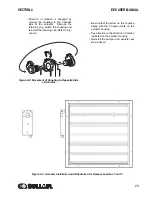
• Direction of rotation is changed by
moving the coupling to the opposite
side of the actuator. Remove the
retaining clip, switch the coupling and
reinstall the retaining clip. Refer to
.
• Be sure that the arrow on the coupling
aligns with the 0 degree mark on the
actuator housing.
• Pay attention to the direction of rotation
indicated on the actuator housing.
• Reinstall the damper and actuator per
step 4 above.
Figure 4-2: Movement of Coupling to Opposite Side
of Actuator
Figure 4-3: Actuator Installation and Orientation for Damper Location 1 and 3
Summary of Contents for 3000 EES
Page 10: ...NOTES 10 ...
Page 16: ...16 BLANK PAGE ...
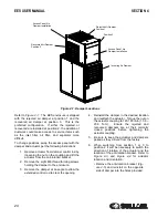
Page 20: ...EES USER MANUAL SECTION 3 20 Figure 3 1 Identification EES 02250175 281 R00 ...
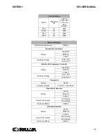
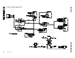
Page 21: ...SECTION 3 EES USER MANUAL 21 Figure 3 2 Wiring Diagram EES 02250175 264 R01 ...
Page 22: ...22 BLANK PAGE ...
Page 28: ...28 BLANK PAGE ...
Page 36: ...36 BLANK PAGE ...
Page 38: ...38 BLANK PAGE ...
Page 44: ...44 BLANK PAGE ...
Page 45: ...Section 8 45 EES USER MANUAL PARTS LISTS ...
Page 46: ...EES USER MANUAL SECTION 8 46 8 1 EES ENCLOSURE ASSEMBLY 02250175 279 R00 ...
Page 48: ...EES USER MANUAL SECTION 8 48 8 2 EES ELECTRICAL CONTROL ASSEMBLY 02250171 648 R00 ...
Page 50: ...EES USER MANUAL SECTION 8 50 8 3 EES DISCHARGE ENCLOSURE ASSEMBLY 02250171 646 R00 ...
Page 52: ...EES USER MANUAL SECTION 8 52 8 4 EES PACKAGE CLEAN AIR INLET OPTION 02250176 044 R00 ...
Page 54: ...54 BLANK PAGE ...
Page 55: ...NOTES 55 ...


