SECTION 4
EES USER MANUAL
27
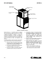
After preparation of the EES enclosure, it is now
ready to install onto the compressor. The enclosure
is shipped from the factory attached to the enclosure
roof panel. Lift the EES enclosure assembly onto the
compressor assembly. Attach to the compressor
with (6) M8 thread forming screws.
4.6
ACTUATOR WIRING AND
CONNECTION
The incoming actuator comes from the factory pre-
wired. The bypass, rejected, and recovered
actuators all come pre-wired with connectors for
easy assembly. The other end of the connectors are
pre-wired with the necessary wire length at the EES
electrical enclosure.
Complete actuator connection as follows:
1. Route wiring along edge of end panel
towards package out. Use wire clips and
nylon ties to secure wires.
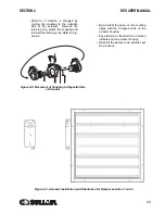
2. Insert connectors and wires through hole in
bypass panel. Attach provided split grommet
to prevent chafing of wires and provide
sealing.
3. Run wires along damper edge using wire
clips as necessary.
4. Each connector end is labeled. Match
connectors, assemble, and hand tighten.
4.7
MIXED AIR TEMPERATURE
SENSOR INSTALLATION
Attach sensor holder to compressor roof panel using
M6 nuts and lock washers. Route mixed air
temperature sensor from EES electrical enclosure.
Use wire clips and nylon ties to secure wires. Route
wire along vertical rail and top rail. Attach sensor to
holder with nylon ties.
4.8
THERMOSTAT PLACEMENT
AND WIRING
Install the thermostat within the space to be heated
where it will sense a representative temperature.
• Do not place thermostat where it could be
exposed to physical damage or tampering.
• Do not place thermostat in recovered air-
flow or other locations which experience
large temperature fluctuations.
It is necessary to wire the thermostat in the EES
electrical enclosure. A separate terminal strip is
provided in the enclosure to simplify this process.
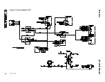
Consult the wiring diagram,
on page 21. Standard 18-22 gauge
thermostat wire is acceptable.
Summary of Contents for 3000 EES
Page 10: ...NOTES 10 ...
Page 16: ...16 BLANK PAGE ...
Page 20: ...EES USER MANUAL SECTION 3 20 Figure 3 1 Identification EES 02250175 281 R00 ...
Page 21: ...SECTION 3 EES USER MANUAL 21 Figure 3 2 Wiring Diagram EES 02250175 264 R01 ...
Page 22: ...22 BLANK PAGE ...
Page 28: ...28 BLANK PAGE ...
Page 36: ...36 BLANK PAGE ...
Page 38: ...38 BLANK PAGE ...
Page 44: ...44 BLANK PAGE ...
Page 45: ...Section 8 45 EES USER MANUAL PARTS LISTS ...
Page 46: ...EES USER MANUAL SECTION 8 46 8 1 EES ENCLOSURE ASSEMBLY 02250175 279 R00 ...
Page 48: ...EES USER MANUAL SECTION 8 48 8 2 EES ELECTRICAL CONTROL ASSEMBLY 02250171 648 R00 ...
Page 50: ...EES USER MANUAL SECTION 8 50 8 3 EES DISCHARGE ENCLOSURE ASSEMBLY 02250171 646 R00 ...
Page 52: ...EES USER MANUAL SECTION 8 52 8 4 EES PACKAGE CLEAN AIR INLET OPTION 02250176 044 R00 ...
Page 54: ...54 BLANK PAGE ...
Page 55: ...NOTES 55 ...


