Section 2
11
EES USER MANUAL
DESCRIPTION
2.1
INTRODUCTION
The Sullair Integral Heat Recovery System is a
means of recovering energy which is expended while
producing compressed air. This energy can be
converted into a useable source of heat. The heat is
stored in the compressor cooling air as it passes over
the compressor motor, fluid cooler and aftercooler.
Latent heat rejected when moisture is condensed
from the compressed air in the aftercooler may also
be recovered. The compressor cooling air may then
be used as preheated makeup air or heating air.
Heat may also be rejected when not required.
Because the heat recovery system is built into the
compressor package it requires a minimal amount of
installation labor. The system has been designed so
that use of auxiliary blowers is not needed as long as
good duct design is practiced.
2.2
APPLICATION
CONSIDERATIONS
G
ENERAL
The Sullair EES is designed primarily to recover the
heat of compression in the form of heated makeup
air. Maximum energy utilization, minimum cost of
installation, and maximum return on investment will
be realized by using the EES in this manner. For
every cubic foot of outside air brought into a building
by the EES, another cubic foot of air that would have
infiltrated into the building at outside temperature will
be eliminated. The fuel savings result from the
primary heating system of the facility
not
having to
heat that cubic foot of air at outside temperature to
the temperature of the heated space.
It is possible for the EES system to operate efficiently
as a heating system; that is, where air is drawn and
heated to some higher temperature (say 90°F
[32°C]), then distributed throughout the heated
space. This usually requires greater capital
investment in the form of a larger ductwork system to
distribute the heated air.
As a preheated makeup air system, air is brought in
from the outside at some low temperature (say 40°F
[14°C]), heated approximately to the heated space
temperature (say 65°F [18°C]), and then released to
the heated space at one location. Since the air is
close to heated space temperature, there is little
advantage in distributing this air throughout the plant.
In either case, the same amount of energy is
recovered, but in the makeup air system, significant
reductions in the installed costs are possible.
It is also possible to utilize the waste heat of
compression for process heating applications such
as drying parts. This type of application will usually
net a greater return on investment because the heat
can be used year round.
DANGER
Any makeup air introduced into a heating or
ventilation system by this system must be
of breathing air quality as defined by appli-
cable codes, laws or regulations.
Summary of Contents for 3000 EES
Page 10: ...NOTES 10 ...
Page 16: ...16 BLANK PAGE ...
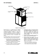
Page 20: ...EES USER MANUAL SECTION 3 20 Figure 3 1 Identification EES 02250175 281 R00 ...
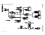
Page 21: ...SECTION 3 EES USER MANUAL 21 Figure 3 2 Wiring Diagram EES 02250175 264 R01 ...
Page 22: ...22 BLANK PAGE ...
Page 28: ...28 BLANK PAGE ...
Page 36: ...36 BLANK PAGE ...
Page 38: ...38 BLANK PAGE ...
Page 44: ...44 BLANK PAGE ...
Page 45: ...Section 8 45 EES USER MANUAL PARTS LISTS ...
Page 46: ...EES USER MANUAL SECTION 8 46 8 1 EES ENCLOSURE ASSEMBLY 02250175 279 R00 ...
Page 48: ...EES USER MANUAL SECTION 8 48 8 2 EES ELECTRICAL CONTROL ASSEMBLY 02250171 648 R00 ...
Page 50: ...EES USER MANUAL SECTION 8 50 8 3 EES DISCHARGE ENCLOSURE ASSEMBLY 02250171 646 R00 ...
Page 52: ...EES USER MANUAL SECTION 8 52 8 4 EES PACKAGE CLEAN AIR INLET OPTION 02250176 044 R00 ...
Page 54: ...54 BLANK PAGE ...
Page 55: ...NOTES 55 ...


