SECTION
1
12
block away from fuel lines, the crank case
breather opening and the battery.
T.
Start the compressor in accordance with normal
procedure. Avoid prolonged cranking.
U.
Allow the compressor to warm up. When the
compressor is warm and operating smoothly at
normal idle RPM, disconnect the jumper cable
from the engine block in the compressor, then
disconnect the other end of this same cable from
the grounded negative (NEG) (-) terminal of the
battery in the starting vehicle. Then disconnect
the other jumper cable from the positive (POS)
(+) terminal of the battery in the compressor, or if
provided with two (2) 12V batteries connected in
series, from the ungrounded battery in the com-
pressor, and finally, disconnect the other end of
this same jumper cable from the positive (POS)
(+) terminal of the battery in the starting vehicle
or from the positive (POS) (+) terminal of the
ungrounded battery in the starting vehicle, if it is
provided with two (2) 12V batteries connected in
series.
V.
Remove and carefully dispose of the dampened
cloths, as they may now be contaminated with
acid, then replace all vent caps.
1.12 IMPLEMENTATION OF
LOCKOUT/TAGOUT
The energy control procedure defines actions
necessary to lockout a power source of any machine
to be repaired, serviced or set-up, where unexpected
motion, or an electrical or other energy source, would
cause personal injury or equipment damage. The
power source on any machine shall be locked out by
each employee doing the work except when motion
is necessary during setup, adjustment or trouble-
shooting.
A.
The established procedures for the application of
energy control shall cover the following elements
and actions and shall be initiated only by Autho-
rized Persons and done in the following
sequence:
1. Review the equipment or machine to be
locked and tagged out.
2. Alert operator and supervisor of which
machine is to be worked on, and that power
and utilities will be turned off.
3. Check to make certain no one is operating
the machine before turning off the power.
4. Turn off the equipment using normal
shutdown procedure.
5. Disconnect the energy sources:
a.
Air and hydraulic lines should be bled,
drained and cleaned out. There should
be no pressure in these lines or in the
reservoir tanks. Lockout or tag lines or
valves.
b.
Any mechanism under tension or pres-
sure, such as springs, should be
released and locked out or tagged.
c.
Block any load or machine part prior to
working under it.
d.
Electrical circuits should be checked with
calibrated electrical testing equipment
and stored energy and electrical capaci-
tors should be safely discharged.
6. Lockout and/or Tagout each energy source
using the proper energy isolating devices
and tags. Place lockout hasp and padlock or
tag at the point of power disconnect where
lockout is required by each person
performing work. Each person shall be
provided with their own padlock and have
possession of the only key. If more than one
person is working on a machine each person
shall affix personal lock and tag using a
multi-lock device.
7. Tagout devices shall be used only when
power sources are not capable of being
locked out by use of padlocks and lockout
hasp devices. The name of the person
affixing tag to power source must be on tag
along with date tag was placed on power
source.
8. Release stored energy and bring the
equipment to a “zero mechanical state”.
9. Verify Isolation: Before work is started, test
equipment to ensure power is disconnected.
B.
General Security
1. The lock shall be removed by the
“Authorized” person who put the lock on the
energy-isolating device. No one other than
the person/persons placing padlocks and
lockout hasps on power shall remove
padlock and lockout hasps and restore
power. However, when the authorized
person who applied the lock is unavailable to
remove it his/her Supervisor may remove
padlock/padlocks and lockout hasps and
restore power only if it is first:
Summary of Contents for 300HH
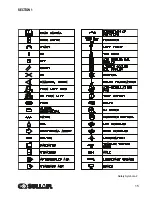
Page 17: ...SECTION 1 15 Safety Symbols 2 ...
Page 18: ...SECTION 1 16 Safety Symbols 3 ...
Page 49: ...SECTION 2 300HH 375 375H 375HH 425 AND 425H USER MANUAL R00 47 2 9 WIRING DIAGRAM ...
Page 60: ...NOTES 58 ...
Page 79: ...NOTES ...


