SECTION 1
5
I.
Make sure tires are in good condition and are the
size (load range) specified and are inflated to the
specified pressures.
DO NOT
change the tire
size or type. Also, make sure wheel bolts, lugs or
nuts are tightened to the specified torques.
J.
If provided, make sure all dual stop, tail direc-
tional and clearance lights are operating properly
and that their lenses are clean and functional.
Also, make sure all reflectors and reflecting sur-
faces, including the slow moving vehicle emblem
on compressors provided with same, are clean
and functional.
K.
Make sure all service air hoses (not air brake
hoses) are disconnected or are fully stowed and
secured on hose reels, if provided.
L.
Make sure all access doors and tool box covers
are closed and latched. If the compressor is
large enough to hold a man, make sure all per-
sonnel are out before closing and latching
access doors.
M.
Make sure parking brakes in towing vehicle are
set, or that its wheels are chocked or blocked, or
that it is otherwise restrained from moving. Then,
release the compressor parking brakes, if pro-
vided.
N.
Make sure the compressor wheels are not
chocked or blocked, and that all tie-downs, if any,
are free.
O.
Test running brake operation, including break-
away switch operation if provided, before
attempting to tow the compressor at its rated
speed or less when conditions prevail.
P. DO NOT
carry loose or inappropriate tools,
equipment or supplies on or in the compressor.
Q. DO NOT
load this equipment with accessories or
tools such that it is unbalanced from side to side
or front to back. Such unbalance will reduce the
towability of this equipment and may increase
the possibility of tipping, rolling over, jackknifing,
etc. Loss of control of the towing vehicle may
result.
T
OWING
A.
Observe all Federal, State, and Local laws while
towing this equipment (including those specifying
minimum speed).
B. DO NOT
exceed the towing speeds listed below
under ideal conditions. Reduce your speed
according to posted speed limits, weather, traffic,
road or terrain conditions:
1. Two axle four-wheel or three axle six-wheel
steerable models: 15 MPH (24 km/h).
2. All other models: 55 MPH (88 km/h).
C.
Remember that the portable air compressor may
approach or exceed the weight of the towing
vehicle. Maintain increased stopping distances
accordingly.
DO NOT
make sudden lane
changes, U-turns or other maneuvers. Such
maneuvers can cause the compressor to tip, roll
over, jackknife or slide and cause loss of control
of the towing vehicle. Tipping, rolling over, etc.
can occur suddenly without warning. U-turns
especially should be made slowly and carefully.
D.
Avoid grades in excess of 15° (27%).
E.
Avoid potholes, rocks and other obstructions,
and soft shoulders or unstable terrain.
F.
Maneuver in a manner that will not exceed the
freedom of motion of the compressor’s drawbar
and/ or coupling device, in or on the towing vehi-
cle’s coupling device and/or adjacent structure
whether towing forward or backing up, regard-
less of the terrain being traversed.
G. DO NOT
permit personnel to ride in or on the
compressor.
H.
Make sure the area behind, in front of, and under
the compressor is clear of all personnel and
obstructions prior to towing in any direction.
I.
DO NOT
permit personnel to stand or ride on the
drawbar, or to stand or walk between the com-
pressor and the towing vehicle.
P
ARKING
O
R
L
OCATING
C
OMPRESSOR
A.
Park or locate compressor on a level surface, if
possible. If not, park or locate compressor across
grade so the compressor does not tend to roll
downhill.
DO NOT
park or locate compressor on
grades exceeding 15° (27%).
B.
Make sure compressor is parked or located on a
firm surface that can support its weight.
C.
Park or locate compressor so the wind, if any,
tends to carry the exhaust fumes and radiator
heat away from the compressor air inlet open-
ings, and also where the compressor will not be
exposed to excessive dust from the work site.
D.
On steerable models, park compressor with front
wheels in straight-ahead position.
Summary of Contents for 300HH
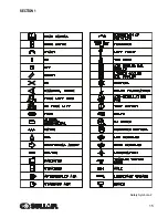
Page 17: ...SECTION 1 15 Safety Symbols 2 ...
Page 18: ...SECTION 1 16 Safety Symbols 3 ...
Page 49: ...SECTION 2 300HH 375 375H 375HH 425 AND 425H USER MANUAL R00 47 2 9 WIRING DIAGRAM ...
Page 60: ...NOTES 58 ...
Page 79: ...NOTES ...


