SECTION
1
6
E.
Set parking brakes and disconnect breakaway
switch cable and all other interconnecting electri-
cal and/or brake connections, if provided.
F.
Block or chock both sides of all wheels.
G.
If provided, unhook chains and remove them
from the points of chain attachment on the towing
vehicle, then hook chains to bail on drawbar or
wrap chains around the drawbar and hook them
to themselves to keep chains off the ground
which might accelerate rusting.
H.
Lower front screw jack and/or any front and rear
stabilizer legs. Make sure the surface they con-
tact has sufficient load bearing capability to sup-
port the weight of the compressor.
I.
If a caster wheel is provided on the screw jack, it
is part of the screw jack and cannot be removed.
Follow the same procedure for stowing away the
wheeled jack as you would for the standard screw
jack. Raise the screw jack to its full upright posi-
tion and pull the pin connecting the jack to the
drawbar. Rotate the screw jack to its stowed posi-
tion, parallel to the drawbar and reinsert the pin.
Make sure the jack is secured in place prior to
towing.
J.
Disconnect coupling device, keeping hands and
fingers clear of all pinch points. If the compressor
is provided with a drawbar,
DO NOT
attempt to lift
the drawbar or if hinged, to raise it to the upright
position by hand, if the weight is more than you
can safely handle. Use a screwjack or chain fall if
you cannot lift or raise the drawbar without avoid-
ing injury to yourself or others.
K.
Move the towing vehicle well clear of the parked
compressor and erect hazard indicators, barri-
cades and/or flares (if at night) if compressor is
parked on or adjacent to public roads. Park so as
not to interfere with traffic.
1.3
PRESSURE RELEASE
A.
Open the pressure relief valve at least weekly to
make sure it is not blocked, closed, obstructed or
otherwise disabled.
B.
Install an appropriate flow-limiting valve between
the compressor service air outlet and the shutoff
(throttle) valve, when an air hose exceeding 1/2"
(13 mm) inside diameter is to be connected to the
shutoff (throttle) valve, to reduce pressure in case
of hose failure, per OSHA Standard 29 CFR
1926.302 (b) (7) or any applicable Federal, State
and Local codes, standards and regulations.
C.
When the hose is to be used to supply a manifold,
install an additional appropriate flow-limiting valve
between the manifold and each air hose exceed-
ing 1/2" (13 mm) inside diameter that is to be con-
nected to the manifold to reduce pressure in case
of hose failure.
D.
Provide an appropriate flow-limiting valve for each
additional 75 feet (23 m) of hose in runs of air
hose exceeding 1/2" (13 mm) inside diameter to
reduce pressure in case of hose failure.
WARNING
This equipment may be tongue heavy. DO
NOT attempt to raise or lower the drawbar
by hand if the weight is more than you can
safely handle.
CAUTION
Retract the front screw jack only after
attaching the compressor to the tow vehi-
cle. Raise the screw jack to its full up posi-
tion and pull the pin connecting the jack to
the drawbar. Rotate the screw jack to its
stowed position, parallel to the drawbar,
and reinsert the pin. Make sure the jack is
secured in place prior to towing.
On two-wheeled models, fully retract front
screw jack and any rear stabilizer legs. If a
caster wheel is provided on the screw jack
it is part of the screw jack and can not be
removed. Follow the same procedure for
stowing away the wheeled jack as you
would for the standard screw jack. Pull the
pin connecting the jack to the drawbar and
raise the screw jack to its full up position.
Rotate the screw jack to its stowed posi-
tion, parallel to the drawbar, and reinsert
the pin. Make sure the jack is secured in
place prior to towing.
NOTE
While not towed in the usual sense of the
word, many of these instructions are
directly applicable to skidmounted porta-
ble air compressors as well.
Summary of Contents for 300HH
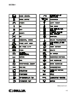
Page 17: ...SECTION 1 15 Safety Symbols 2 ...
Page 18: ...SECTION 1 16 Safety Symbols 3 ...
Page 49: ...SECTION 2 300HH 375 375H 375HH 425 AND 425H USER MANUAL R00 47 2 9 WIRING DIAGRAM ...
Page 60: ...NOTES 58 ...
Page 79: ...NOTES ...


