Section 4
300HH, 375, 375H, 375HH, 425 AND 425H USER MANUAL R00
59
GENERAL
4.1
GENERAL
While Sullair has built into this compressor a
complete set of controls and indicators that allow the
operator to control and monitor the compressor’s
operation and performance. Operators should learn
to recognize indications which identify a service
requirement or conditions that could lead to (or show)
a (current) malfunction. Before starting the
compressor, read this section thoroughly to gain
familiarity with the controls and indicators—their
function and location.
4.2
PURPOSE OF CONTROLS
C
ONTROL
OR
I
NDICATOR
P
URPOSE
E
NGINE
S
WITCH
Press this switch to the ON (ignition) position to
energize the electrical system of the compressor.
Press the switch to the START position to
momentarily engage the starter and start the
compressor. Press the switch to the OFF position to
shut the compressor down. This switch is located on
the instrument panel.
E
MERGENCY
S
TOP
S
WITCH
Press in case of emergency when immediate
shutdown is required.
P
RESSURE
T
RANSDUCER
Monitors the system control pressure.
S
PEED
M
ODULE
Monitors the pressure transducer output and
determines the appropriate speed signal for the
engine.
A
IR
P
RESSURE
G
AUGE
Continuously monitors the pressure inside the
receiver tank at various load and unload conditions.
F
LUID
S
IGHT
L
EVEL
G
LASS
Indicates the fluid level in the receiver tank. Proper
level is marked halfway up the sight glass. Check the
level when the compressor is shutdown and on level
ground.
C
OMPRESSOR
D
ISCHARGE
T
EMPERATURE
S
WITCH
Opens the electrical circuit to shut down the
compressor when the discharge temperature
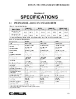
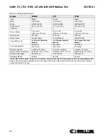
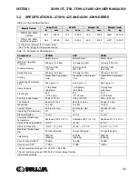
reaches a specific value (See Specifications on page
53 and on page 55).
T
HERMAL
V
ALVE
Functions as a temperature regulator by directing the
compressor fluid either to the cooler or to the
compressor unit.
M
INIMUM
P
RESSURE
D
EVICE
Maintains the minimum of 80 psig (5.6 bar) in the
compressor sump.
P
RESSURE
R
ELIEF
V
ALVE
Vents sump pressure to the atmosphere if pressure
inside the sump exceeds 250 psig (17.3 bar).
A
IR
I
NLET
V
ALVE
Regulates the amount of air allowed to enter the air
compressor inlet. Regulation is determined by a
signal from the pressure regulator(s).
P
RESSURE
R
EGULATOR
(
S
)
Allows the pressure signal to reach the engine speed
transducer and the air inlet valve to control air
delivery according to demand.
D
ISCHARGE
A
IR
F
ILTER
D
IFFERENTIAL
P
RESSURE
G
AUGE
(O
PTIONAL
A
FTERCOOLED
AND
F
ILTERED
M
ODELS
O
NLY
)
Monitors the air filter (first and second stage)
condition. A reading over 10 psig (0.7 bar) in the red
zone indicates the air filters require servicing.
S
HUTDOWN
S
YSTEM
/A
NNUNCIATOR
M
ODULE
(SSAM)
Monitors the compressor safety system for
conditions requiring shutdown. The annunciator on
the instrument control will flash the applicable
shutdown code.
B
LOWDOWN
V
ALVE
Vents sump pressure to the atmosphere at
shutdown.
Summary of Contents for 300HH
Page 17: ...SECTION 1 15 Safety Symbols 2 ...
Page 18: ...SECTION 1 16 Safety Symbols 3 ...
Page 49: ...SECTION 2 300HH 375 375H 375HH 425 AND 425H USER MANUAL R00 47 2 9 WIRING DIAGRAM ...
Page 60: ...NOTES 58 ...
Page 79: ...NOTES ...


