Section 4
COMPRESSOR SYSTEMS
11
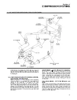
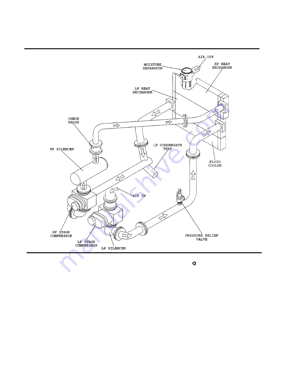
4---4 LP and HP Silencing/Discharge Air and Cooling Systems
A decrease in compressor inlet pressure, caused
by the collected airborne dirt, is sensed by the Su-
pervisor
II
and a filter maintenance announcement
is displayed.
4.5 LOAD/UNLOAD CAPACITY CONTROL SYSTEM,
FUNCTIONAL DESCRIPTION
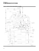
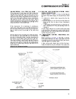
Refer to Figure
. The purpose of the capacity
control system is to regulate the compressed air
supply to the demand. It consists of an inlet
throttling valve and hydraulic actuator assembly,
and a discharge blowdown valve and muffler as-
sembly, all controlled by the Supervisor
II
. The dif-
ferent phases of operation are described below (for
illustration purposes, 100 psi service operation will
be used):
START MODE -- 0 TO 5 PSIG (0 TO 0.34 BAR)
When the
“I”
or
“
”
pads are depressed, the unit
starts. The inlet valve cylinder control solenoid
valve is deenergized. The blowdown valve remains
open, reducing air compression at the HP pipe-
work, and the inlet valve remains nearly closed (hy-
dro actuator retracted), nearly shutting off inlet air
to the unit.
FULL LOAD MODE -- 75 TO 100 PSIG (5.2--6.9
BAR)
After a two second interval, the Supervisor
II
ener-
gizes the inlet valve cylinder control solenoid valve
which opens the inlet valve (hydro actuator ex-
tended), and closes the blowdown valve via the lim-
it switch, allowing the package to intake and com-
press at 100% capacity.
Summary of Contents for DR-13 Series
Page 6: ...NOTES ...
Page 14: ...8 NOTES ...
Page 18: ...Section 4 COMPRESSOR SYSTEMS 12 Figure 4 5 Piping and Instrumentation Diagram Air cooled ...
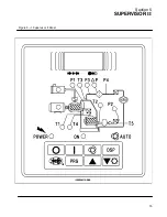
Page 21: ...Section 5 SUPERVISOR II 15 Figure 5 1 Supervisor II Panel ...
Page 28: ...22 NOTES ...
Page 32: ...26 NOTES ...
Page 42: ...Section 7 MAINTENANCE 36 Table 1 Installation Data ...
Page 46: ...40 NOTES ...
Page 48: ...Section 9 ILLUSTRATIONS AND PARTS LIST 42 9 3 COMPRESSOR MOTOR AND FRAME ...
Page 50: ...Section 9 ILLUSTRATIONS AND PARTS LIST 44 9 4 AIR INLET SYSTEM ...
Page 52: ...Section 9 ILLUSTRATIONS AND PARTS LIST 46 9 5 COOLER ASSEMBLY ...
Page 54: ...Section 9 ILLUSTRATIONS AND PARTS LIST 48 9 6 LP HOT LP COLD ...
Page 56: ...Section 9 ILLUSTRATIONS AND PARTS LIST 50 9 7 HP DISCHARGE ...
Page 58: ...Section 9 ILLUSTRATIONS AND PARTS LIST 52 9 8 LUBE SYSTEM ...
Page 60: ...Section 9 ILLUSTRATIONS AND PARTS LIST 54 9 9 ELECTRICAL BOX ...
Page 62: ...Section 9 ILLUSTRATIONS AND PARTS LIST 56 9 10 CONTROL SYSTEM CONDENSATE DRAIN ...
Page 64: ...Section 9 ILLUSTRATIONS AND PARTS LIST 58 9 11 CANOPY ...
Page 66: ...Section 9 ILLUSTRATIONS AND PARTS LIST 60 9 12 DECALS ...
Page 68: ...Section 9 ILLUSTRATIONS AND PARTS LIST 62 9 12 DECALS ...
Page 70: ...Section 9 ILLUSTRATIONS AND PARTS LIST 64 9 12 DECALS ...
Page 72: ...Section 9 ILLUSTRATIONS AND PARTS LIST 66 9 13 DECAL LOCATIONS ...
Page 74: ...Section 9 ILLUSTRATIONS AND PARTS LIST 68 9 13 DECAL LOCATIONS ...
Page 76: ...Section 9 ILLUSTRATIONS AND PARTS LIST 70 9 13 DECAL LOCATIONS ...
Page 78: ...Section 9 ILLUSTRATIONS AND PARTS LIST 72 9 14 WIRING DIAGRAM ...
Page 79: ...NOTES ...


