Section 5
SUPERVISOR
II
17
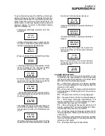
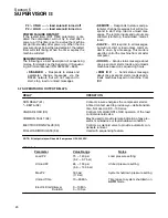
To view other status press the DSP key. All temper-
atures and pressures may be displayed as well as
other status information. To scroll through the dis-
plays press the up arrow or down arrow keys. Up
arrow moves to the next display, down arrow the
previous display. To return to the default display
press the display key.
S
Interstage discharge pressure and line
pressure.
P1 30
P2 110
S
Oil filter differential pressure and the maxi-
mum limit. If the limit is exceeded oil main-
tenance warning will be displayed.
dP2 4
MAX 20
S
Pressure before (P4) and after (P3) oil filter.
P3 40
P4 44
S
Interstage discharge temperature. Shuts
off the compressor it T1 exceeds T1 MAX
and system status will display T1 HI.
T1 350
MAX 445
S
Final discharge temperature and the maxi-
mum limit. If the temperature exceeds the
limit a T2 HI shutdown will occur.
T2 350
MAX 445
S
Oil temperature and the maximum limit.
If the temperature exceeds the limit a T3 HI
shutdown will occur.
T3 100
MAX 160
S
Interstage temperature after the intercool-
er and the maximum limit. If the tempera-
ture exceeds the limit a T4 HI shutdown will
occur.
T4 100
MAX 160
S
Package discharge temperature and the
maximum limit. If the temperature exceeds
the limit a T5 HI shutdown will occur.
T5 100
MAX 160
S
Total hours that the compressor has been
running.
HRS RUN
001234.0
S
Total hours that the compressor has been
loaded.
HRS LOAD
000987.0
S
Last fault log. This shows the fault on the
first line and the run hours when the fault
occcured.
T1 HI
@1 234
S
Next to last fault log. This shows the fault
on the first line and the run hours when the
fault occcured.
T1 HI
@2 204
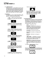
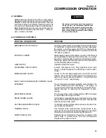
5.4 LAMP INDICATORS
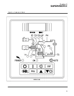
Embedded into the front panel schematic of the
compressor are several lamps. Pressing the lamp
test key will light all the lamps for 3 seconds. Each
LED lamp has the following purpose.
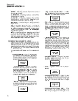
P1
--- (Interstage pressure) If lit steady, signifies
that P1 is being displayed, if flashing denotes the
presence of an alarm.
P2
--- (Line pressure) If lit steady, signifies that P2 is
being displayed, if flashing denotes the presence
of an alarm.
P3
--- Pressure after oil filter is being displayed.
P4
--- Pressure before oil filter is being displayed.
T1
--- (First stage discharge temperature) If lit
steady, signifies that T1 is being displayed, if flash-
ing denotes the presence of an alarm.
T2
--- (Second stage discharge temperature) If lit
steady, signifies that T2 is being displayed, if flash-
ing denotes the presence of an alarm.
T3
--- (Oil temperature) If lit steady, signifies that T3
is being displayed, if flashing denotes the presence
of an alarm.
T4
--- (Interstage temperature) If lit steady, signifies
that T4 is being displayed, if flashing denotes the
presence of an alarm.
T5
--- (Package discharge temperature)
Summary of Contents for DR-13 Series
Page 6: ...NOTES ...
Page 14: ...8 NOTES ...
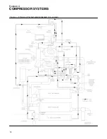
Page 18: ...Section 4 COMPRESSOR SYSTEMS 12 Figure 4 5 Piping and Instrumentation Diagram Air cooled ...
Page 21: ...Section 5 SUPERVISOR II 15 Figure 5 1 Supervisor II Panel ...
Page 28: ...22 NOTES ...
Page 32: ...26 NOTES ...
Page 42: ...Section 7 MAINTENANCE 36 Table 1 Installation Data ...
Page 46: ...40 NOTES ...
Page 48: ...Section 9 ILLUSTRATIONS AND PARTS LIST 42 9 3 COMPRESSOR MOTOR AND FRAME ...
Page 50: ...Section 9 ILLUSTRATIONS AND PARTS LIST 44 9 4 AIR INLET SYSTEM ...
Page 52: ...Section 9 ILLUSTRATIONS AND PARTS LIST 46 9 5 COOLER ASSEMBLY ...
Page 54: ...Section 9 ILLUSTRATIONS AND PARTS LIST 48 9 6 LP HOT LP COLD ...
Page 56: ...Section 9 ILLUSTRATIONS AND PARTS LIST 50 9 7 HP DISCHARGE ...
Page 58: ...Section 9 ILLUSTRATIONS AND PARTS LIST 52 9 8 LUBE SYSTEM ...
Page 60: ...Section 9 ILLUSTRATIONS AND PARTS LIST 54 9 9 ELECTRICAL BOX ...
Page 62: ...Section 9 ILLUSTRATIONS AND PARTS LIST 56 9 10 CONTROL SYSTEM CONDENSATE DRAIN ...
Page 64: ...Section 9 ILLUSTRATIONS AND PARTS LIST 58 9 11 CANOPY ...
Page 66: ...Section 9 ILLUSTRATIONS AND PARTS LIST 60 9 12 DECALS ...
Page 68: ...Section 9 ILLUSTRATIONS AND PARTS LIST 62 9 12 DECALS ...
Page 70: ...Section 9 ILLUSTRATIONS AND PARTS LIST 64 9 12 DECALS ...
Page 72: ...Section 9 ILLUSTRATIONS AND PARTS LIST 66 9 13 DECAL LOCATIONS ...
Page 74: ...Section 9 ILLUSTRATIONS AND PARTS LIST 68 9 13 DECAL LOCATIONS ...
Page 76: ...Section 9 ILLUSTRATIONS AND PARTS LIST 70 9 13 DECAL LOCATIONS ...
Page 78: ...Section 9 ILLUSTRATIONS AND PARTS LIST 72 9 14 WIRING DIAGRAM ...
Page 79: ...NOTES ...


