Section 5
SUPERVISOR
II
20
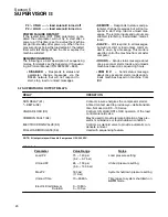
P2 > UNLD -- --> load solenoid turned off
P2 < LOAD -- --> load solenoid turned on
POWER FAILURE RESTART
If the restart timer (RST TIME parameter) is dis-
abled the compressor will not try to start after a
power up. If this time is set to a value the machine
will go into standby after power up. When the line
pressure drops below the load setpoint, the restart
timer will start timing. When the timer expires the
machine will start.
SEQUENCING MODES
The following is a brief description of sequencing
modes, for details see the Supervisor II Sequenc-
ing & Protocol Manual (P/N 02250057---696)
.
S
DISABLED
--- Responds to status and
parameter change messages via the
RS485 network but will not respond to
start, stop, load or unload messages.
S
REMOTE
--- Responds to status and pa-
rameter change messages but will not re-
spond to start, stop, load or unload mes-
sages. The remote inputs and outputs are
enabled (start/stop, load/unload, master/
local).
S
SLAVE
--- Will respond to all messages,
but will not start or load unless comman-
ded to do so by a message. This mode is
used to control the machine from a master
computer.
S
HOURS
--- Sends status message about
once a second, starts, loads and unloads
machines based on sequencing hours.
S
COM ID #
--- Sends status message
about once a second, starts, loads and un-
loads machines based on machine Com
ID#.
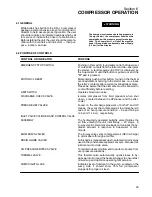
5.7 SUPERVISOR
II
OUTPUT RELAYS
RELAY
OPERATION
RUN RELAY (K1)
Contact closure energizes the compressor starter.
*---DELTA (K2)
A timed contact used to provide wye---delta transition
time. Not used on DS---13 Series.
UNLOAD/LOAD (K3)
Controls ON LOAD/OFF LOAD operaton of the load
control solenoid valve.
COMMON FAULT (K4)
May be used to provide remote indication of any pre---
alarm, maintenance or fault shutdown condition.
ELECTRIC DRAIN VALVE (K5)
Controls a solenoid valve to provide automatic con-
densate removal.
FULL LOAD/MODULATE (K6)
Used with sequencing feature.
NOTE: All output relays will handle 8 amperes at 120/240 VAC.
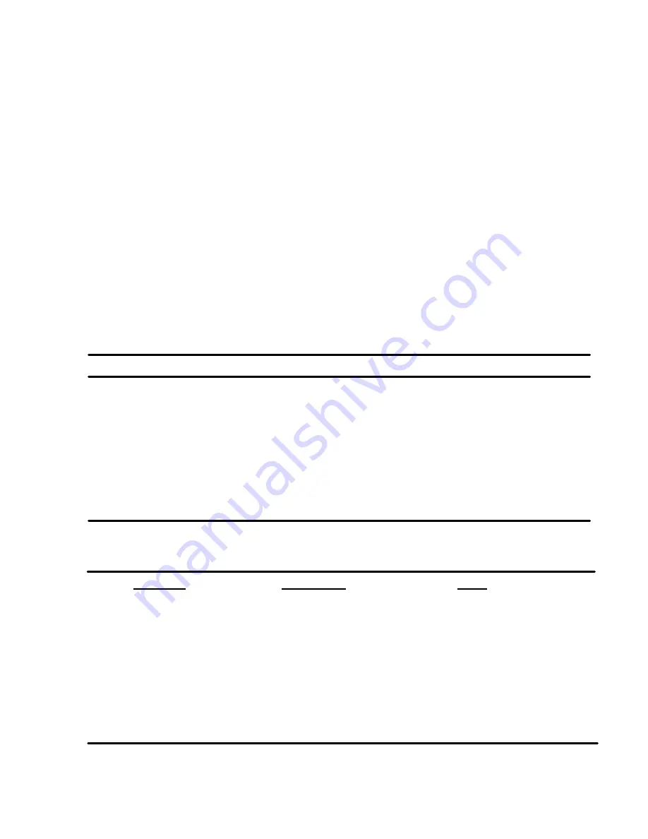
Parameter
Value Range
Notes
Load P2
75 --- 140 psi
Load pressure setting
(5.2 --- 9.7 bar)
Unload P2
85 --- 150 psi
Unload pressure setting
(5.9 --- 10.3 bar)
Max P2
160 psi
System shutdown pressure setting
(11 bar)
Unload Time
10---60 Min.
Time lapse to system shutdown on
AUTO
mode
Table 5---1
Electric DrainInterval
0---10 Min.
0---10 Sec.
Duration
Summary of Contents for DR-13 Series
Page 6: ...NOTES ...
Page 14: ...8 NOTES ...
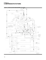
Page 18: ...Section 4 COMPRESSOR SYSTEMS 12 Figure 4 5 Piping and Instrumentation Diagram Air cooled ...
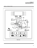
Page 21: ...Section 5 SUPERVISOR II 15 Figure 5 1 Supervisor II Panel ...
Page 28: ...22 NOTES ...
Page 32: ...26 NOTES ...
Page 42: ...Section 7 MAINTENANCE 36 Table 1 Installation Data ...
Page 46: ...40 NOTES ...
Page 48: ...Section 9 ILLUSTRATIONS AND PARTS LIST 42 9 3 COMPRESSOR MOTOR AND FRAME ...
Page 50: ...Section 9 ILLUSTRATIONS AND PARTS LIST 44 9 4 AIR INLET SYSTEM ...
Page 52: ...Section 9 ILLUSTRATIONS AND PARTS LIST 46 9 5 COOLER ASSEMBLY ...
Page 54: ...Section 9 ILLUSTRATIONS AND PARTS LIST 48 9 6 LP HOT LP COLD ...
Page 56: ...Section 9 ILLUSTRATIONS AND PARTS LIST 50 9 7 HP DISCHARGE ...
Page 58: ...Section 9 ILLUSTRATIONS AND PARTS LIST 52 9 8 LUBE SYSTEM ...
Page 60: ...Section 9 ILLUSTRATIONS AND PARTS LIST 54 9 9 ELECTRICAL BOX ...
Page 62: ...Section 9 ILLUSTRATIONS AND PARTS LIST 56 9 10 CONTROL SYSTEM CONDENSATE DRAIN ...
Page 64: ...Section 9 ILLUSTRATIONS AND PARTS LIST 58 9 11 CANOPY ...
Page 66: ...Section 9 ILLUSTRATIONS AND PARTS LIST 60 9 12 DECALS ...
Page 68: ...Section 9 ILLUSTRATIONS AND PARTS LIST 62 9 12 DECALS ...
Page 70: ...Section 9 ILLUSTRATIONS AND PARTS LIST 64 9 12 DECALS ...
Page 72: ...Section 9 ILLUSTRATIONS AND PARTS LIST 66 9 13 DECAL LOCATIONS ...
Page 74: ...Section 9 ILLUSTRATIONS AND PARTS LIST 68 9 13 DECAL LOCATIONS ...
Page 76: ...Section 9 ILLUSTRATIONS AND PARTS LIST 70 9 13 DECAL LOCATIONS ...
Page 78: ...Section 9 ILLUSTRATIONS AND PARTS LIST 72 9 14 WIRING DIAGRAM ...
Page 79: ...NOTES ...


