Section 5
SUPERVISOR
II
21
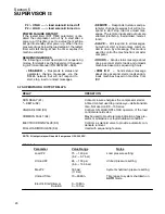
5.8 SUPERVISOR II CONTROL PARAMETERS-- DS--13
SENSOR
FUNCTION
UNITS
PREALARM
SHUTDOWN
FAILURE
MODE
P1
Interstage Air Pressure
psig/bar
49/ 3.4
52/ 3.6
Hi
P2
Discharge Air Pressure
psig/bar
N/A
50/ 3.4
Lo
P3
Oil Filter Outlet Pressure
psig/bar
N/A
25/ 1.7
Lo
P4
Oil Filter Inlet Pressure
psig/bar
N/A
N/A
N/A
Dp1
Inet Filter Vacuum
inches H
2
O
15
N/A
Hi
Dp2
Oil Filter Differential (P4---P3)
psig/bar
20/ 1.4
N/A
Hi
T1
1
st
Stage Discharge Air Temp.
˚
F/
˚
C
435/ 224
445/ 229
Hi
T2
2
nd
Stage Discharge Air Temp.
˚
F/
˚
C
435/ 224
445/ 229
Hi
T3
Oil Filter Outlet Temp.
˚
F/
˚
C
155/ 68
160/ 71
Hi
T4
2
nd
Stage Inlet Air Temp.
˚
F/
˚
C
155/ 68
160/ 71
Hi
T5
Aftercooler Discharge Temp.
˚
F/
˚
C
155/ 68
160/ 71
Hi
Summary of Contents for DR-13 Series
Page 6: ...NOTES ...
Page 14: ...8 NOTES ...
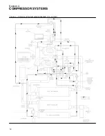
Page 18: ...Section 4 COMPRESSOR SYSTEMS 12 Figure 4 5 Piping and Instrumentation Diagram Air cooled ...
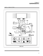
Page 21: ...Section 5 SUPERVISOR II 15 Figure 5 1 Supervisor II Panel ...
Page 28: ...22 NOTES ...
Page 32: ...26 NOTES ...
Page 42: ...Section 7 MAINTENANCE 36 Table 1 Installation Data ...
Page 46: ...40 NOTES ...
Page 48: ...Section 9 ILLUSTRATIONS AND PARTS LIST 42 9 3 COMPRESSOR MOTOR AND FRAME ...
Page 50: ...Section 9 ILLUSTRATIONS AND PARTS LIST 44 9 4 AIR INLET SYSTEM ...
Page 52: ...Section 9 ILLUSTRATIONS AND PARTS LIST 46 9 5 COOLER ASSEMBLY ...
Page 54: ...Section 9 ILLUSTRATIONS AND PARTS LIST 48 9 6 LP HOT LP COLD ...
Page 56: ...Section 9 ILLUSTRATIONS AND PARTS LIST 50 9 7 HP DISCHARGE ...
Page 58: ...Section 9 ILLUSTRATIONS AND PARTS LIST 52 9 8 LUBE SYSTEM ...
Page 60: ...Section 9 ILLUSTRATIONS AND PARTS LIST 54 9 9 ELECTRICAL BOX ...
Page 62: ...Section 9 ILLUSTRATIONS AND PARTS LIST 56 9 10 CONTROL SYSTEM CONDENSATE DRAIN ...
Page 64: ...Section 9 ILLUSTRATIONS AND PARTS LIST 58 9 11 CANOPY ...
Page 66: ...Section 9 ILLUSTRATIONS AND PARTS LIST 60 9 12 DECALS ...
Page 68: ...Section 9 ILLUSTRATIONS AND PARTS LIST 62 9 12 DECALS ...
Page 70: ...Section 9 ILLUSTRATIONS AND PARTS LIST 64 9 12 DECALS ...
Page 72: ...Section 9 ILLUSTRATIONS AND PARTS LIST 66 9 13 DECAL LOCATIONS ...
Page 74: ...Section 9 ILLUSTRATIONS AND PARTS LIST 68 9 13 DECAL LOCATIONS ...
Page 76: ...Section 9 ILLUSTRATIONS AND PARTS LIST 70 9 13 DECAL LOCATIONS ...
Page 78: ...Section 9 ILLUSTRATIONS AND PARTS LIST 72 9 14 WIRING DIAGRAM ...
Page 79: ...NOTES ...


