Section 6
COMPRESSOR OPERATION
25
13. Open service valve to air net system. Compres-
sor will run loaded or unloaded as the system
demands.
14. Check operating conditions and reinspect for
leaks the following day.
6.5 SYSTEM STATUS MESSAGES
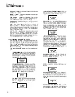
The top row of the display is for the System Status
Messages. These messages tell what mode the
compressor is in, if maintenance is required, or if
the compressor is “shutdown” due to an operating
parameter violation. True first---out indication of a
fault shutdown is assured by displaying only the
first condition of shutdown on the message display.
Subsequent fault conditions may appear as LED
indications on the graphic map.
The following messages indicate that everything is
normal:
MANUAL
--- Compressor is off, in manual mode.
STANDBY
--- Compressor is off, in automatic
mode.
OFF LOAD
--- Compressor is on, the load solenoid
valves are de---energized.
ON LOAD
--- Compressor is on, the load solenoid
valves are energized.
The following messages indicate that the compres-
sor may need maintenance: The messages are
cleared by pressing
“O”
.
AIR MNTN
--- Air filter maintenance indication; in-
spect and/or change air filter elements.
OIL MNTN--
Oil filter maintenance indication; in-
spect and/or change oil filter element.
The following messages indicate that the compres-
sor has exceeded an operational limit. Pressing
“O”
will clear these messages, but only if the condi-
tion causing these messages is no longer present.
The compressor will not run if any of these mes-
sages are still present.
P1 HI
--- P1 was greater than 52 psig (3.6 bar).
P1 prealarm occurs at 49 psig (3.4 bar).
T1 HI
--- T1 was greater than 445
_
F (229
_
C).
T1 prealarm occurs at 435
_
F (224
_
C).
T2 HI
--- T2 was greater than 445
_
F (229
_
C). T2
prealarm occurs at 435
_
F (224
_
C).
E--STOP
--- The emergency stop pushbutton was
pushed in.
MOTOR OL
--- The motor overload contact has
opened.
COOL FLT
--- Cooling fan motor overload contact
was opened.
P1--LOW
--- P1
<
25 psig (1.7 bar) while running.
This will also occur if the motor fails to run when the
RUN relay is energized. An alternate cause for this
condition may be a defective P1 transducer.
P2--LOW
--- The machine ran continuously for five
minutes at a final pressure below 50 psig (3.4 bar).
T1 or T2 FAIL
--- T1
±
6
_
F while the compressor
was running. Since this is an impossibly low value,
the Supervisor assumes that the temperature
probe has failed.
P1 FAIL
--- P1
²
198 psig (13.7 bar) while the com-
pressor is stopped. Since this is an impossibly high
value, the Supervisor assumes that the pressure
transducer has failed.
P2 FAIL
--- P2
²
198 psig (13.7 bar) while the com-
pressor is stopped. Since this is an impossibly high
value, the Supervisor assumes that the pressure
transducer has failed.
P3 FAIL
--- P3
±
25 psig (1.7 bar) while the com-
pressor is running.
6.6 SUBSEQUENT START--UP PROCEDURE
On subsequent start---ups, check that the steady---
state indications supplied by the Supervisor
II
and
local gauges are satisfactory. Also check for proper
lubricant level in the sump.
6.7 SHUTDOWN PROCEDURE
To shut the package down, simply press the
“O”
pad.
Summary of Contents for DR-13 Series
Page 6: ...NOTES ...
Page 14: ...8 NOTES ...
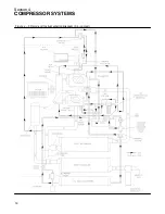
Page 18: ...Section 4 COMPRESSOR SYSTEMS 12 Figure 4 5 Piping and Instrumentation Diagram Air cooled ...
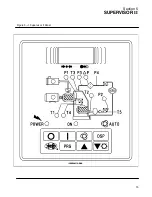
Page 21: ...Section 5 SUPERVISOR II 15 Figure 5 1 Supervisor II Panel ...
Page 28: ...22 NOTES ...
Page 32: ...26 NOTES ...
Page 42: ...Section 7 MAINTENANCE 36 Table 1 Installation Data ...
Page 46: ...40 NOTES ...
Page 48: ...Section 9 ILLUSTRATIONS AND PARTS LIST 42 9 3 COMPRESSOR MOTOR AND FRAME ...
Page 50: ...Section 9 ILLUSTRATIONS AND PARTS LIST 44 9 4 AIR INLET SYSTEM ...
Page 52: ...Section 9 ILLUSTRATIONS AND PARTS LIST 46 9 5 COOLER ASSEMBLY ...
Page 54: ...Section 9 ILLUSTRATIONS AND PARTS LIST 48 9 6 LP HOT LP COLD ...
Page 56: ...Section 9 ILLUSTRATIONS AND PARTS LIST 50 9 7 HP DISCHARGE ...
Page 58: ...Section 9 ILLUSTRATIONS AND PARTS LIST 52 9 8 LUBE SYSTEM ...
Page 60: ...Section 9 ILLUSTRATIONS AND PARTS LIST 54 9 9 ELECTRICAL BOX ...
Page 62: ...Section 9 ILLUSTRATIONS AND PARTS LIST 56 9 10 CONTROL SYSTEM CONDENSATE DRAIN ...
Page 64: ...Section 9 ILLUSTRATIONS AND PARTS LIST 58 9 11 CANOPY ...
Page 66: ...Section 9 ILLUSTRATIONS AND PARTS LIST 60 9 12 DECALS ...
Page 68: ...Section 9 ILLUSTRATIONS AND PARTS LIST 62 9 12 DECALS ...
Page 70: ...Section 9 ILLUSTRATIONS AND PARTS LIST 64 9 12 DECALS ...
Page 72: ...Section 9 ILLUSTRATIONS AND PARTS LIST 66 9 13 DECAL LOCATIONS ...
Page 74: ...Section 9 ILLUSTRATIONS AND PARTS LIST 68 9 13 DECAL LOCATIONS ...
Page 76: ...Section 9 ILLUSTRATIONS AND PARTS LIST 70 9 13 DECAL LOCATIONS ...
Page 78: ...Section 9 ILLUSTRATIONS AND PARTS LIST 72 9 14 WIRING DIAGRAM ...
Page 79: ...NOTES ...

