Section 7
MAINTENANCE
27
7.1 GENERAL
As you proceed to study this section, it will be easy to
see that maintenance for the air compressor is quite
minimal. The Supervisor II monitors the status of the
air and oil filters. When maintenance to either device
is required, the Supervisor II will display the appropri-
ate maintenance message and flash the location
LED on the graphics map as a visual remainder.
WARNING
!
DO NOT remove caps, plugs, and/or other compo-
nents when compressor is running or pressurized.
Stop compressor and relieve all internal pressure
before doing so.
7.2 DAILY OPERATION
Following a routine start, observe the various Super-
visor II displays and local gauges to check that nor-
mal readings are been made -- previous records are
very helpful in determining the normalcy of the mea-
surements. These observations should be made
during all expected modes of operation (i.e. full load,
no--load, different line pressures, cooling water tem-
peratures, etc.).
7.3 INITIAL MAINTENANCE AFTER 50 HOURS OF
OPERATION
Upon completion of the first 50 hours of operation, a
few maintenance requirements are needed to rid the
system of any foreign materials which may have ac-
cumulated during assembly:
1. Change the lubricant filter element.
2. Clean the control line filter element.
3. Check/replace the sump breather element.
7.4 MAINTENANCE EVERY 8000 HOURS OR ONE
YEAR OF OPERATION
The following items should be checked every 8000
hours of operation or one year, whichever comes
first, although service conditions such as relative
cleanliness of process air or quality of cooling me-
dium may require shorter inspection intervals.
1. Replace oil charge and filter element.
2. Replace control line filter element.
3. Replace sump breather filter element.
4. Replace air filter element.
5. Check/clean condensate drain valves screen.
6. Check condition of shaft coupling element and
tightness of fasteners.
7. Measure and record vibration signatures on com-
pressor, gear box and motor -- optional.
NOTE
Please refer to the motor manufacturer’s docu-
mentation for recommended maintenance. Keep
in mind that the specified type and quantity of lu-
bricating grease for motor anti--friction bearings is
crucial.
7.5 MAINTENANCE EVERY 16000 HOURS OR TWO
YEARS OF OPERATION
In addition to those items covered by the 8000 hour
or one year maintenance interval, the following items
must also be checked every 16000 hours of opera-
tion or two years, depending upon conditions of ser-
vice:
1. Operate/test all safety devices.
2. Check/clean heat exchangers.
3. Check/clean blowdown valve.
4. Check/clean check valves.
5. Check condition of isolation mounts under com-
pressor unit and motor.
6. Check/clean strainer included in oil pump suction
line, inside oil sump.
7.6 DIAGNOSTIC SERVICE (OPTIONAL)
Sullair and its representatives offer a diagnostic ser-
vice to check the condition of your compressor unit.
The service, which is recommended at 8000 hour in-
tervals, performs the following:
1. Tri--axial vibration measurements at the gearbox
and the compressor stages.
2. Package performance data collection and analy-
sis.
3. Examination of shaft coupling assembly.
4. Operational check of protective equipment.
5. Final discussion with maintenance engineer.
This service, when supplemented by properly re-
corded package operational performance and vibra-
tions trends, is most helpful in identifying the pres-
ence (or absence) of equipment damage which can
be repaired or replaced before a catastrophic break-
down occurs.
7.7 PARTS REPLACEMENT AND ADJUSTMENT
PROCEDURES
Please, familiarize yourself with the safety guidelines
offered in Section 1 of this manual before attempting
any maintenance on the package.
7.7.1 AIR FILTER INSPECTION/MAINTENANCE
ELEMENT INSPECTION
1. Place a bright light inside the elements to inspect
for damage or leak holes.
2. Inspect gaskets and matching sealing surfaces on
the housing. It should be smooth or replace in
case of damage.
3. The secondary element must be replaced if dirt ob-
struction is evident.
4.
DO NOT
strike elements against a hard surface to
dislodge dirt -- this may damage the sealing sur-
faces and/or rupture the element.
AIR FILTER MAINTENANCE
Refer to Figure
. Air filter maintenance should be
performed at 8000 hours, one year or when the cor-
responding maintenance message is displayed by
the Supervisor II. This corresponds to a pressure
loss condition across the filter of 22 in. (56 cm) of wa-
ter. Your filter assembly includes a primary element
and a secondary element.
1. Clean exterior of filter housing.
2. Loosen retaining band and remove cover with rub-
ber dust collector attached.
3. Remove wing nut, washer and primary element.
4. Clean interior of housing with a damp cloth.
5. Remove wing nut, washer and secondary ele-
ment.
Summary of Contents for DR-13 Series
Page 6: ...NOTES ...
Page 14: ...8 NOTES ...
Page 18: ...Section 4 COMPRESSOR SYSTEMS 12 Figure 4 5 Piping and Instrumentation Diagram Air cooled ...
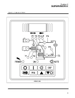
Page 21: ...Section 5 SUPERVISOR II 15 Figure 5 1 Supervisor II Panel ...
Page 28: ...22 NOTES ...
Page 32: ...26 NOTES ...
Page 42: ...Section 7 MAINTENANCE 36 Table 1 Installation Data ...
Page 46: ...40 NOTES ...
Page 48: ...Section 9 ILLUSTRATIONS AND PARTS LIST 42 9 3 COMPRESSOR MOTOR AND FRAME ...
Page 50: ...Section 9 ILLUSTRATIONS AND PARTS LIST 44 9 4 AIR INLET SYSTEM ...
Page 52: ...Section 9 ILLUSTRATIONS AND PARTS LIST 46 9 5 COOLER ASSEMBLY ...
Page 54: ...Section 9 ILLUSTRATIONS AND PARTS LIST 48 9 6 LP HOT LP COLD ...
Page 56: ...Section 9 ILLUSTRATIONS AND PARTS LIST 50 9 7 HP DISCHARGE ...
Page 58: ...Section 9 ILLUSTRATIONS AND PARTS LIST 52 9 8 LUBE SYSTEM ...
Page 60: ...Section 9 ILLUSTRATIONS AND PARTS LIST 54 9 9 ELECTRICAL BOX ...
Page 62: ...Section 9 ILLUSTRATIONS AND PARTS LIST 56 9 10 CONTROL SYSTEM CONDENSATE DRAIN ...
Page 64: ...Section 9 ILLUSTRATIONS AND PARTS LIST 58 9 11 CANOPY ...
Page 66: ...Section 9 ILLUSTRATIONS AND PARTS LIST 60 9 12 DECALS ...
Page 68: ...Section 9 ILLUSTRATIONS AND PARTS LIST 62 9 12 DECALS ...
Page 70: ...Section 9 ILLUSTRATIONS AND PARTS LIST 64 9 12 DECALS ...
Page 72: ...Section 9 ILLUSTRATIONS AND PARTS LIST 66 9 13 DECAL LOCATIONS ...
Page 74: ...Section 9 ILLUSTRATIONS AND PARTS LIST 68 9 13 DECAL LOCATIONS ...
Page 76: ...Section 9 ILLUSTRATIONS AND PARTS LIST 70 9 13 DECAL LOCATIONS ...
Page 78: ...Section 9 ILLUSTRATIONS AND PARTS LIST 72 9 14 WIRING DIAGRAM ...
Page 79: ...NOTES ...

