Section 7
MAINTENANCE
32
It is not necessary to remove the valve from the pipe
line for repairs.
DISASSEMBLY
Prior to performing this, be sure all pressure is re-
moved from the system.
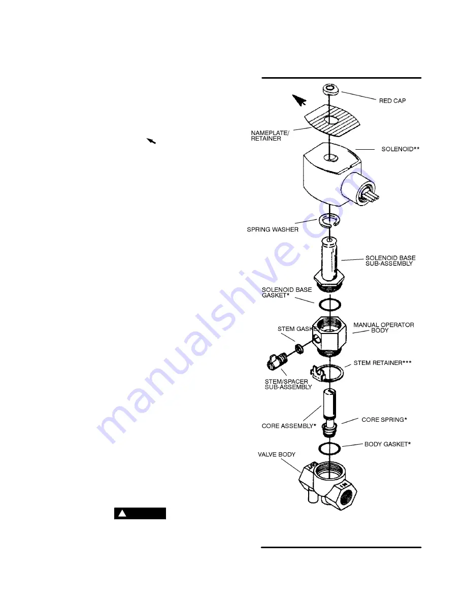
1. Remove the retaining cap. Push down on the coil
while prying the nameplate/retainer cover in the
direction of the arrow [
] (See Figure
Nameplate/retainer cover will slip forward, releas-
ing the coil assembly. Slip the coil assembly off of
the solenoid base subassembly.
2. Unscrew the solenoid base assembly. Remove
the solenoid base gasket, core/insert sub-assem-
bly, core spring and insert gasket.
3. All parts are now accessible for cleaning or re-
placement.
REASSEMBLY
1. Lubricate all gaskets with Dow Corning
r
111 Com-
pound lubricant, or equivalent high-grade silicone
grease. If replacing parts, exchange worn or dam-
aged parts with new parts found in the replace-
ment kit, and/or replacement coil.
2. Snap insert gasket into the groove of the core/in-
sert sub-assembly. Be sure to use the proper size
gasket.
3. Install core/insert sub-assembly into body cavity
and push it gently down until the gasket of the in-
sert just seals in the cavity of the body.
4. Install core spring in top of core/insert into top of
core/insert sub-assembly. Close end of core
spring protrudes from top of core.
5. Install solenoid base gasket and solenoid base
sub-assembly. Torque solenoid base sub-assem-
bly to 260
±
25 in.-lbs. (30
±
3 Nm).
6. Re--install solenoid.
7.7.6 SOLENOID VALVE (P/N 02250044-392) MAINTE-
NANCE
Refer to Figure
. Solenoid valve maintenance is
quite minimal, but a periodic cleaning is desireable.
The time between cleanings will vary depending on
operating conditions. In general, if the voltage to the
coils is correct, sluggish valve operation will indicate
that cleaing is required. Disassemble valve and
clean all parts. If parts are worn or damaged, order
replacement kit no. 02250044-391, and replacement
coil no. 250031-738.
WARNING
!
Turn off all power, relieve line pressure, and dis-
connect coil lead wires to the valve before making
repairs.
Figure 7-6 Solenoid Valve (P/N 02250044-392)
*Replacement Kit P/N 02250044-391
**Replacement Coil P/N 250031-738
***Refer to Figure 7-7 for re-assembly notes.
Summary of Contents for DR-13 Series
Page 6: ...NOTES ...
Page 14: ...8 NOTES ...
Page 18: ...Section 4 COMPRESSOR SYSTEMS 12 Figure 4 5 Piping and Instrumentation Diagram Air cooled ...
Page 21: ...Section 5 SUPERVISOR II 15 Figure 5 1 Supervisor II Panel ...
Page 28: ...22 NOTES ...
Page 32: ...26 NOTES ...
Page 42: ...Section 7 MAINTENANCE 36 Table 1 Installation Data ...
Page 46: ...40 NOTES ...
Page 48: ...Section 9 ILLUSTRATIONS AND PARTS LIST 42 9 3 COMPRESSOR MOTOR AND FRAME ...
Page 50: ...Section 9 ILLUSTRATIONS AND PARTS LIST 44 9 4 AIR INLET SYSTEM ...
Page 52: ...Section 9 ILLUSTRATIONS AND PARTS LIST 46 9 5 COOLER ASSEMBLY ...
Page 54: ...Section 9 ILLUSTRATIONS AND PARTS LIST 48 9 6 LP HOT LP COLD ...
Page 56: ...Section 9 ILLUSTRATIONS AND PARTS LIST 50 9 7 HP DISCHARGE ...
Page 58: ...Section 9 ILLUSTRATIONS AND PARTS LIST 52 9 8 LUBE SYSTEM ...
Page 60: ...Section 9 ILLUSTRATIONS AND PARTS LIST 54 9 9 ELECTRICAL BOX ...
Page 62: ...Section 9 ILLUSTRATIONS AND PARTS LIST 56 9 10 CONTROL SYSTEM CONDENSATE DRAIN ...
Page 64: ...Section 9 ILLUSTRATIONS AND PARTS LIST 58 9 11 CANOPY ...
Page 66: ...Section 9 ILLUSTRATIONS AND PARTS LIST 60 9 12 DECALS ...
Page 68: ...Section 9 ILLUSTRATIONS AND PARTS LIST 62 9 12 DECALS ...
Page 70: ...Section 9 ILLUSTRATIONS AND PARTS LIST 64 9 12 DECALS ...
Page 72: ...Section 9 ILLUSTRATIONS AND PARTS LIST 66 9 13 DECAL LOCATIONS ...
Page 74: ...Section 9 ILLUSTRATIONS AND PARTS LIST 68 9 13 DECAL LOCATIONS ...
Page 76: ...Section 9 ILLUSTRATIONS AND PARTS LIST 70 9 13 DECAL LOCATIONS ...
Page 78: ...Section 9 ILLUSTRATIONS AND PARTS LIST 72 9 14 WIRING DIAGRAM ...
Page 79: ...NOTES ...

