Section 8
TROUBLESHOOTING
37
8.1 INTRODUCTION
The following information has been compiled
from operational experience with your package.
It identifies symptoms and describes probable
causes for problems. However
DO NOT
assume
that these are the only problems that may occur.
The collection of operational data concerning
possible trouble should be analyzed to prevent
complete compressor breakdown. An example
of this would be the vibrations signature in-
crease of a damaged bearing or the efficiency
decrease of a dirty heat exchanger.
A detailed visual inspection should be per-
formed for all problems. Always remember to:
1. Check for loose wiring.
2. Check for damaged piping.
3. Check for parts damaged by heat or an electri-
cal short circuit, usually apparent by discolor-
ation or a burnt odor.
Should your problem persist after making the
recommended check, consult your nearest Sull-
air representative or the Sullair Corporation.
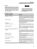
8.2 TROUBLESHOOTING
SYMPTOM/MESSAGE
PROBABLE CAUSE
REMEDY
COMPRESSOR WILL NOT START;
Main Disconnect Switch Open
Close switch.
POWER LED OFF
Line Fuse Blown
Replace fuse.
Control Transformer Fuse Blown
Replace fuse.
MOTOR OL
Motor Starter Overloads Tripped
Reset after heater elements cool
down. Should trouble persist, check
whether motor starter contacts are
functioning properly.
Low Incoming Line Voltage
Check voltage. Should voltage check
low, consult power company.
T---1, T---2, T---3
Temperature Transducer Failure
Check connections from
T---4, T---5 FAIL
transducer. If adequate, replace
transducer.
P---1, P---2, P---3
Pressure Transducer Failure
Check connections from
P---4 FAIL
transducer. If adequate, replace
transducer.
E---STOP
Emergency Switch Open
Close switch (pull).
(Depressed)
COOL FLT
Cooling Fan Motor Starter Overloads
Reset after heater elements cool
Tripped
down. Should trouble persist, check
whether motor starter contacts are
functioning properly.
COMPRESSOR SHUTS DOWN
Motor Starter Overloads Tripped
Reset after heater elements cool
WITH AIR DEMAND:
down. Should trouble persist,
MOTOR OL
check whether motor starter contacts
are functioning properly.
(I)
Low Incoming Line Voltage
Check voltage. Should voltage
check low, consult power company.
P2 LO
The Machine Ran at a Final Discharge
Adjust valve downstream of package to
Pressure Below 50 psig (3.4 bar) for
hold minimum 70 psig (4.8 bar) line
five minutes
pressure.
P3 LO
Oil Pressure Falls Below 25 psig
(1.7 bar) While Package is Running
Because:
Oil Pump Malfunctioned
Consult Sullair Service Dept.
Oil Filter Clogged
Replace filter element.
(I)
Also check that the compressor---motor driveline rotates freely. In case of rotating resistance or rubbing, contact
Sullair Service Department.
Summary of Contents for DR-13 Series
Page 6: ...NOTES ...
Page 14: ...8 NOTES ...
Page 18: ...Section 4 COMPRESSOR SYSTEMS 12 Figure 4 5 Piping and Instrumentation Diagram Air cooled ...
Page 21: ...Section 5 SUPERVISOR II 15 Figure 5 1 Supervisor II Panel ...
Page 28: ...22 NOTES ...
Page 32: ...26 NOTES ...
Page 42: ...Section 7 MAINTENANCE 36 Table 1 Installation Data ...
Page 46: ...40 NOTES ...
Page 48: ...Section 9 ILLUSTRATIONS AND PARTS LIST 42 9 3 COMPRESSOR MOTOR AND FRAME ...
Page 50: ...Section 9 ILLUSTRATIONS AND PARTS LIST 44 9 4 AIR INLET SYSTEM ...
Page 52: ...Section 9 ILLUSTRATIONS AND PARTS LIST 46 9 5 COOLER ASSEMBLY ...
Page 54: ...Section 9 ILLUSTRATIONS AND PARTS LIST 48 9 6 LP HOT LP COLD ...
Page 56: ...Section 9 ILLUSTRATIONS AND PARTS LIST 50 9 7 HP DISCHARGE ...
Page 58: ...Section 9 ILLUSTRATIONS AND PARTS LIST 52 9 8 LUBE SYSTEM ...
Page 60: ...Section 9 ILLUSTRATIONS AND PARTS LIST 54 9 9 ELECTRICAL BOX ...
Page 62: ...Section 9 ILLUSTRATIONS AND PARTS LIST 56 9 10 CONTROL SYSTEM CONDENSATE DRAIN ...
Page 64: ...Section 9 ILLUSTRATIONS AND PARTS LIST 58 9 11 CANOPY ...
Page 66: ...Section 9 ILLUSTRATIONS AND PARTS LIST 60 9 12 DECALS ...
Page 68: ...Section 9 ILLUSTRATIONS AND PARTS LIST 62 9 12 DECALS ...
Page 70: ...Section 9 ILLUSTRATIONS AND PARTS LIST 64 9 12 DECALS ...
Page 72: ...Section 9 ILLUSTRATIONS AND PARTS LIST 66 9 13 DECAL LOCATIONS ...
Page 74: ...Section 9 ILLUSTRATIONS AND PARTS LIST 68 9 13 DECAL LOCATIONS ...
Page 76: ...Section 9 ILLUSTRATIONS AND PARTS LIST 70 9 13 DECAL LOCATIONS ...
Page 78: ...Section 9 ILLUSTRATIONS AND PARTS LIST 72 9 14 WIRING DIAGRAM ...
Page 79: ...NOTES ...


