Section 2
INSTALLATION
5
2.1 MOUNTING OF COMPRESSOR
The compressor package should be placed on a
surface or foundation that is capable of supporting
its weight, while remaining level and free of deflec-
tions which may affect the driveline mounts or the
inboard pipework.
If the package is to be secured to a foundation, it is
recommended that the package frame be leveled
and secured to the foundation with adequate an-
chorage, and that a good grade grouting be used
to insure full contact between the load bearing sur-
faces. Use 3/4” (19mm) foundation bolts.
The DR compressor/motor driveline is self---al-
igned by the use of a rigid distance piece and sup-
ported by flexible vibration isolation mounts. Poor
leveling or excessive deflections may adversely af-
fect the operation and longevity of these devices.
No piping loads or moments should be transmitted
to the air and water connections provided with the
package.
2.2 VENTILATION AND COOLING
Select a location that allows an unrestricted flow of
ambient ventilation
air through the package
(approximately 18,000 CFM). The maximum allow-
able ambient temperature is 115
_
F (46
_
C). Heat
rejection to the surrounding environment will be up
to 20% greater than the motor horsepower (this is
because of the latent heat of condensation of the
moisture removed from the intake air and the heat
from the motor inefficiency). The 200HP model will
discharge up to 615,000 BTU/hr to the surrounding
environment (smaller models correspondingly
less).
Maintain a 3ft. (914mm) minimum separation be-
tween the package and any surrounding walls.
Note that the electrical enclosure has a 32.5 in
(826mm) access door hinged on its right side.
WARNING
!
Note that the cooling air intake to the package and
the hot air discharge are both on top of the pack-
age. There should be no restriction to the free
flow of cooling air and discharge air, and care
should be taken to ensure that cooling air and dis-
charge air remain separate.
If ductwork is installed, the total restriction on in-
take and outlet combined must not exceed 0.12 in
H
2
O (30 Pascals).
2.3 SERVICE AIR CONDENSATE PIPING
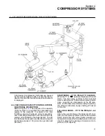
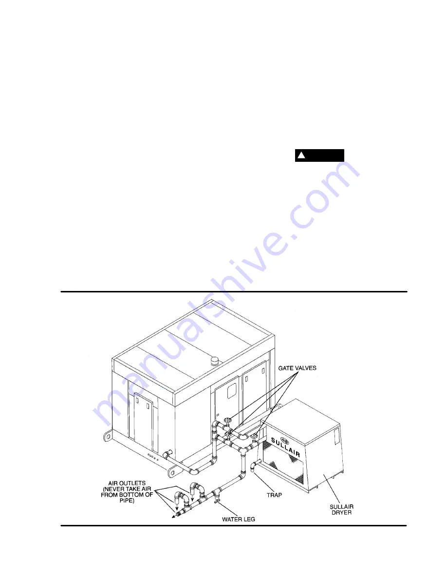
It is recommended that service air piping be in-
stalled as shown in Fig
. A shut---off valve
should be included to isolate the package from the
supply line as required. The use of water legs and
Figure 2---1 Service Air Piping (Typical)
Summary of Contents for DR-13 Series
Page 6: ...NOTES ...
Page 14: ...8 NOTES ...
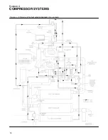
Page 18: ...Section 4 COMPRESSOR SYSTEMS 12 Figure 4 5 Piping and Instrumentation Diagram Air cooled ...
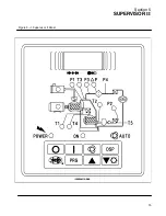
Page 21: ...Section 5 SUPERVISOR II 15 Figure 5 1 Supervisor II Panel ...
Page 28: ...22 NOTES ...
Page 32: ...26 NOTES ...
Page 42: ...Section 7 MAINTENANCE 36 Table 1 Installation Data ...
Page 46: ...40 NOTES ...
Page 48: ...Section 9 ILLUSTRATIONS AND PARTS LIST 42 9 3 COMPRESSOR MOTOR AND FRAME ...
Page 50: ...Section 9 ILLUSTRATIONS AND PARTS LIST 44 9 4 AIR INLET SYSTEM ...
Page 52: ...Section 9 ILLUSTRATIONS AND PARTS LIST 46 9 5 COOLER ASSEMBLY ...
Page 54: ...Section 9 ILLUSTRATIONS AND PARTS LIST 48 9 6 LP HOT LP COLD ...
Page 56: ...Section 9 ILLUSTRATIONS AND PARTS LIST 50 9 7 HP DISCHARGE ...
Page 58: ...Section 9 ILLUSTRATIONS AND PARTS LIST 52 9 8 LUBE SYSTEM ...
Page 60: ...Section 9 ILLUSTRATIONS AND PARTS LIST 54 9 9 ELECTRICAL BOX ...
Page 62: ...Section 9 ILLUSTRATIONS AND PARTS LIST 56 9 10 CONTROL SYSTEM CONDENSATE DRAIN ...
Page 64: ...Section 9 ILLUSTRATIONS AND PARTS LIST 58 9 11 CANOPY ...
Page 66: ...Section 9 ILLUSTRATIONS AND PARTS LIST 60 9 12 DECALS ...
Page 68: ...Section 9 ILLUSTRATIONS AND PARTS LIST 62 9 12 DECALS ...
Page 70: ...Section 9 ILLUSTRATIONS AND PARTS LIST 64 9 12 DECALS ...
Page 72: ...Section 9 ILLUSTRATIONS AND PARTS LIST 66 9 13 DECAL LOCATIONS ...
Page 74: ...Section 9 ILLUSTRATIONS AND PARTS LIST 68 9 13 DECAL LOCATIONS ...
Page 76: ...Section 9 ILLUSTRATIONS AND PARTS LIST 70 9 13 DECAL LOCATIONS ...
Page 78: ...Section 9 ILLUSTRATIONS AND PARTS LIST 72 9 14 WIRING DIAGRAM ...
Page 79: ...NOTES ...


