Section 2
INSTALLATION
6
drain traps is also recommended throughout.
No piping loads or moments should be transmitted
to the air connections provided with the package.
Condensate drains shall be connected to a non---
pressurized gravity feed drain. If the compressor
drains are manifolded together, care should be tak-
en to insure that this drain is not pressurized when
the machine condensate drains (both automatic or
manual) are in operation.
All condensate should be disposed of in accor-
dance with local governing laws.
2.4 SHAFT COUPLING ALIGNMENT CHECK
The compressor unit and motor are rigidly con-
nected via a cast adaptor piece which maintains
the shaft coupling in proper alignment. It is recom-
mended that prior to initial startup shaft alignment
be checked, and all coupling fasteners are
checked for proper tensioning. Refer to the Cou-
pling Service Procedures included in the Mainte-
nance section of this manual.
2.5 FLUID LEVEL CHECK
The package oil sump is supplied with the proper
charge of lube oil --- a level reaching 75% of the
sight glass should be visible when the compressor
unit is shut down. Check this level after initial instal-
lation and periodically thereafter.
2.6 ELECTRICAL PREPARATION
Interior electrical wiring is assembled at the factory.
Required customer wiring is minimal (i.e., isolation
switches, fusible disconnects, etc.), but should be
done by a qualified electrician, in compliance with
OSHA, NEC, and any other applicable codes. A
wiring diagram is provided with the package docu-
mentation.
DANGER
!
Lethal shock hazard inside.
Disconnect all power at source before opening or
servicing.
1. Make sure incoming field voltage matches re-
quired package voltage.
2. Check starter overload and heater sizes --- see
Electrical section in Parts Manual.
3. Check all electrical connections for tightness.
4. Check motor rotation, as explained in Section
2.7.
2.7 MOTOR ROTATION CHECK
After the electrical installation has been done, it is
necessary to check the direction of motor rotation.
Pull out the EMERGENCY STOP button and press
once, quickly and in succession, the
“I”
and
“O”
pads. This action will “Bump Start” the motor for a
very short time. When looking at the motor from the
rear end, the driveline should be rotating counter-
clockwise (opposite shaft end). If the reversed ro-
tation is noted, disconnect the power to the starter
and exchange any two of the three power input
leads, then re---check rotation. A “Direction of Ro-
tation” nameplate is located on the top of the com-
pressor/motor adaptor piece.
Summary of Contents for DR-13 Series
Page 6: ...NOTES ...
Page 14: ...8 NOTES ...
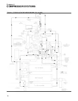
Page 18: ...Section 4 COMPRESSOR SYSTEMS 12 Figure 4 5 Piping and Instrumentation Diagram Air cooled ...
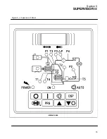
Page 21: ...Section 5 SUPERVISOR II 15 Figure 5 1 Supervisor II Panel ...
Page 28: ...22 NOTES ...
Page 32: ...26 NOTES ...
Page 42: ...Section 7 MAINTENANCE 36 Table 1 Installation Data ...
Page 46: ...40 NOTES ...
Page 48: ...Section 9 ILLUSTRATIONS AND PARTS LIST 42 9 3 COMPRESSOR MOTOR AND FRAME ...
Page 50: ...Section 9 ILLUSTRATIONS AND PARTS LIST 44 9 4 AIR INLET SYSTEM ...
Page 52: ...Section 9 ILLUSTRATIONS AND PARTS LIST 46 9 5 COOLER ASSEMBLY ...
Page 54: ...Section 9 ILLUSTRATIONS AND PARTS LIST 48 9 6 LP HOT LP COLD ...
Page 56: ...Section 9 ILLUSTRATIONS AND PARTS LIST 50 9 7 HP DISCHARGE ...
Page 58: ...Section 9 ILLUSTRATIONS AND PARTS LIST 52 9 8 LUBE SYSTEM ...
Page 60: ...Section 9 ILLUSTRATIONS AND PARTS LIST 54 9 9 ELECTRICAL BOX ...
Page 62: ...Section 9 ILLUSTRATIONS AND PARTS LIST 56 9 10 CONTROL SYSTEM CONDENSATE DRAIN ...
Page 64: ...Section 9 ILLUSTRATIONS AND PARTS LIST 58 9 11 CANOPY ...
Page 66: ...Section 9 ILLUSTRATIONS AND PARTS LIST 60 9 12 DECALS ...
Page 68: ...Section 9 ILLUSTRATIONS AND PARTS LIST 62 9 12 DECALS ...
Page 70: ...Section 9 ILLUSTRATIONS AND PARTS LIST 64 9 12 DECALS ...
Page 72: ...Section 9 ILLUSTRATIONS AND PARTS LIST 66 9 13 DECAL LOCATIONS ...
Page 74: ...Section 9 ILLUSTRATIONS AND PARTS LIST 68 9 13 DECAL LOCATIONS ...
Page 76: ...Section 9 ILLUSTRATIONS AND PARTS LIST 70 9 13 DECAL LOCATIONS ...
Page 78: ...Section 9 ILLUSTRATIONS AND PARTS LIST 72 9 14 WIRING DIAGRAM ...
Page 79: ...NOTES ...


