Section 3
SPECIFICATIONS
7
3.1 SULLAIR DR--13 COMPRESSOR PACKAGE
DIMENSIONS
MAXIMUM
DR---13--- SERIES 60 Hz
OPERATING
TYPE
HP
LENGTH
WIDTH
HEIGHT
WEIGHT
PRESSURE
IN/CM
IN/CM
IN/CM
LB/KG
PSI
DR13 100H
100
144/366
72/183
80/
203
9350/4250
125
DR13 125H
125
144/366
72/183
80/
203
9900/4500
125
DR13 125HH
125
144/366
72/183
80/
203
9900/4500
150
DR13 150H
150
144/366
72/183
80/
203
10100/4690
125
DR13 150HH
150
144/366
72/183
80/
203
10100/4690
150
DR13 200H
200
144/366
72/183
80/
203
10350/4700
125
DR13 200HH
200
144/366
72/183
80/
203
10350/4700
150
MAXIMUM
DR---13--- SERIES 50 Hz
OPERATING
TYPE
HP
LENGTH
WIDTH
HEIGHT
WEIGHT
PRESSURE
IN/CM
IN/CM
IN/CM
KG
BAR
DR13 75H
100
144/366
72/183
80/
203
9750/4430
8.5
DR13 75HH
100
144/366
72/183
80/
203
9750/4430
10.3
DR13 90H
125
144/366
72/183
80/
203
9900/4500
8.5
DR13 90HH
125
144/366
72/183
80/
203
9900/4500
10.3
DR13 110H
150
144/366
72/183
80/
203
10100/4690
8.5
DR13 110HH
150
144/366
72/183
80/
203
10100/4690
10.3
DR13 132H
200
144/366
72/183
80/
203
10350/4700
8.5
DR13 132HH
200
144/366
72/183
80/
203
10350/4700
10.3
COMPRESSOR:
Type:
Positive Displacement, Oil---Free, Twin Rotary Screws
Configuration:
Two---stages, Driven by Single Increaser Gear Box
Bearing Type:
Anti---Friction
Lubrication:
Pressurize System for Bearings, Gears and Cooling Jackets
Sump Capacity:
10 gallons (37.9 liters)
Duty Temperature:
115
_
F (46
_
C) Max.
Control:
Electro---hydro---pneumatic
Discharge Pressure:
Maximum (see Table 3.1); Minimum 70 psi (4.8 bar)
MOTOR:
Type:
TEFC Enclosure, NEMA Frames 365TSC through 445TSC,
Premium Efficient
Size:
100 through 200 HP, 2---pole speed
Voltage:
230V, 460V, 575V, 380V @ 60 Hz; 400V, 380---415V @ 50 Hz
Service:
50
_
C Ambient
Starter:
Solid State Reduced Voltage with Disconnect Switch
3.2 LUBRICATION GUIDE
Sullair DR---13 compressors are factory filled with
Sullair lubricant (no. 02250057---198).
WARNING
!
Mixing of other fluids within the compressor
should be authorized by the factory. Otherwise,
this may void all warranties.
Lubricant should be checked/changed every 8,000
hours or once a year, whichever comes first. The
fluid should be changed more frequently under se-
vere operating conditions, such as high ambient
temperatures coupled with high humidity or when
high particulate level, corrosive gases or strong oxi-
dizing gases are present in the air.
Maintenance of all other components is still recom-
mended as indicated in the Maintenance section of
this manual.
Summary of Contents for DR-13 Series
Page 6: ...NOTES ...
Page 14: ...8 NOTES ...
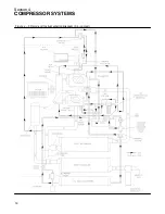
Page 18: ...Section 4 COMPRESSOR SYSTEMS 12 Figure 4 5 Piping and Instrumentation Diagram Air cooled ...
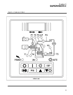
Page 21: ...Section 5 SUPERVISOR II 15 Figure 5 1 Supervisor II Panel ...
Page 28: ...22 NOTES ...
Page 32: ...26 NOTES ...
Page 42: ...Section 7 MAINTENANCE 36 Table 1 Installation Data ...
Page 46: ...40 NOTES ...
Page 48: ...Section 9 ILLUSTRATIONS AND PARTS LIST 42 9 3 COMPRESSOR MOTOR AND FRAME ...
Page 50: ...Section 9 ILLUSTRATIONS AND PARTS LIST 44 9 4 AIR INLET SYSTEM ...
Page 52: ...Section 9 ILLUSTRATIONS AND PARTS LIST 46 9 5 COOLER ASSEMBLY ...
Page 54: ...Section 9 ILLUSTRATIONS AND PARTS LIST 48 9 6 LP HOT LP COLD ...
Page 56: ...Section 9 ILLUSTRATIONS AND PARTS LIST 50 9 7 HP DISCHARGE ...
Page 58: ...Section 9 ILLUSTRATIONS AND PARTS LIST 52 9 8 LUBE SYSTEM ...
Page 60: ...Section 9 ILLUSTRATIONS AND PARTS LIST 54 9 9 ELECTRICAL BOX ...
Page 62: ...Section 9 ILLUSTRATIONS AND PARTS LIST 56 9 10 CONTROL SYSTEM CONDENSATE DRAIN ...
Page 64: ...Section 9 ILLUSTRATIONS AND PARTS LIST 58 9 11 CANOPY ...
Page 66: ...Section 9 ILLUSTRATIONS AND PARTS LIST 60 9 12 DECALS ...
Page 68: ...Section 9 ILLUSTRATIONS AND PARTS LIST 62 9 12 DECALS ...
Page 70: ...Section 9 ILLUSTRATIONS AND PARTS LIST 64 9 12 DECALS ...
Page 72: ...Section 9 ILLUSTRATIONS AND PARTS LIST 66 9 13 DECAL LOCATIONS ...
Page 74: ...Section 9 ILLUSTRATIONS AND PARTS LIST 68 9 13 DECAL LOCATIONS ...
Page 76: ...Section 9 ILLUSTRATIONS AND PARTS LIST 70 9 13 DECAL LOCATIONS ...
Page 78: ...Section 9 ILLUSTRATIONS AND PARTS LIST 72 9 14 WIRING DIAGRAM ...
Page 79: ...NOTES ...


