Section 4
COMPRESSOR SYSTEMS
13
UNLOAD MODE -- 100+ PSIG (6.9+ BAR)
If the demand of compressed air falls below that
supplied by the package, the line pressure (P2) in-
creases. When the line pressure reaches the 100
psig (6.9 bar) setting programmed in the Supervi-
sor
II
, the inlet valve cylinder control solenoid is
deenergized, which closes the inlet valve (hydro
actuator retracted), and opens the blowdown valve
via the limit switch, unloading the package to the
state described in the Start Mode.
If the Supervisor
II
is operating in continuous
mode, the compressor runs unloaded until the line
(P2) pressure falls below the 90 psig (6.2 bar) set-
ting, at which point it proceeds to the Full Load
Mode.
If the Supervisor
II
is operating in automatic mode,
the compressor runs unloaded for a standard fac-
tory pre---set length of time, and the line pressure
(P2) does not fall below the 90 psig (6.2 bar) set-
ting, the compressor will stop at the end of this peri-
od. When the line pressure (P2) falls below the 90
psig (6.2 bar) setting, a Start Mode automatically
takes place, followed by package operation in the
Full Load Mode.
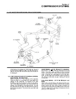
4.6 COOLING AND SILENCING SYSTEM, FUNC-
TIONAL DESCRIPTION
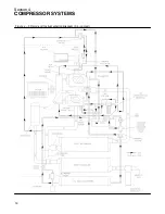
Refer to Figure
and
. As air is discharged
by each compressor stage, it is sequentially routed
to:
S
a silencer to reduce noise caused by the dis-
charged air.
S
heat exchangers to cool the high temperature air
delivered by the oil---free screw compressor
stages.
S
combination separator/drains to eliminate liq-
uids condensed in the preceeding heat ex-
changers.
The LP stage silencer is a reactive pipework sized
to dampen lower frequency air pulses, while the HP
stage silencer is a reactive vessel sized to dampen
higher frequency pulses.
4.7 LUBRICATION SYSTEM, FUNCTIONAL DE-
SCRIPTION
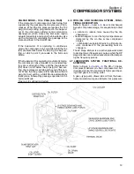
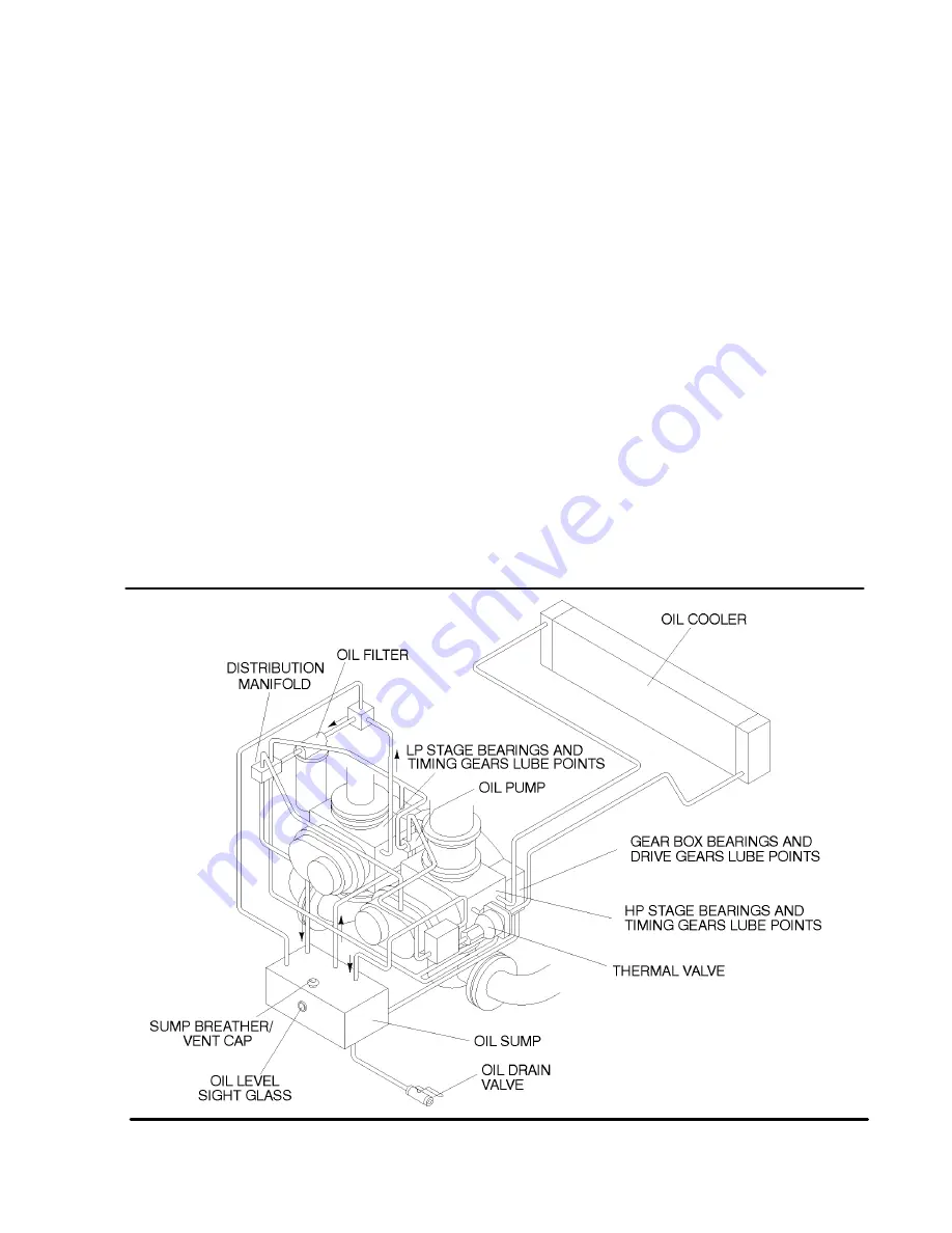
Refer to Figure
and
. The DR---13 Series
Compressor delivers oil---free compressed air, but
it requires lubricant to maintain its high speed bear-
ings and gears in running order.
A gear---type pump draws lube oil from the base-
frame mounted sump and delivers it at a pressure
Figure 4---6 Lubrication System
Summary of Contents for DR-13 Series
Page 6: ...NOTES ...
Page 14: ...8 NOTES ...
Page 18: ...Section 4 COMPRESSOR SYSTEMS 12 Figure 4 5 Piping and Instrumentation Diagram Air cooled ...
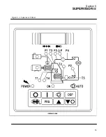
Page 21: ...Section 5 SUPERVISOR II 15 Figure 5 1 Supervisor II Panel ...
Page 28: ...22 NOTES ...
Page 32: ...26 NOTES ...
Page 42: ...Section 7 MAINTENANCE 36 Table 1 Installation Data ...
Page 46: ...40 NOTES ...
Page 48: ...Section 9 ILLUSTRATIONS AND PARTS LIST 42 9 3 COMPRESSOR MOTOR AND FRAME ...
Page 50: ...Section 9 ILLUSTRATIONS AND PARTS LIST 44 9 4 AIR INLET SYSTEM ...
Page 52: ...Section 9 ILLUSTRATIONS AND PARTS LIST 46 9 5 COOLER ASSEMBLY ...
Page 54: ...Section 9 ILLUSTRATIONS AND PARTS LIST 48 9 6 LP HOT LP COLD ...
Page 56: ...Section 9 ILLUSTRATIONS AND PARTS LIST 50 9 7 HP DISCHARGE ...
Page 58: ...Section 9 ILLUSTRATIONS AND PARTS LIST 52 9 8 LUBE SYSTEM ...
Page 60: ...Section 9 ILLUSTRATIONS AND PARTS LIST 54 9 9 ELECTRICAL BOX ...
Page 62: ...Section 9 ILLUSTRATIONS AND PARTS LIST 56 9 10 CONTROL SYSTEM CONDENSATE DRAIN ...
Page 64: ...Section 9 ILLUSTRATIONS AND PARTS LIST 58 9 11 CANOPY ...
Page 66: ...Section 9 ILLUSTRATIONS AND PARTS LIST 60 9 12 DECALS ...
Page 68: ...Section 9 ILLUSTRATIONS AND PARTS LIST 62 9 12 DECALS ...
Page 70: ...Section 9 ILLUSTRATIONS AND PARTS LIST 64 9 12 DECALS ...
Page 72: ...Section 9 ILLUSTRATIONS AND PARTS LIST 66 9 13 DECAL LOCATIONS ...
Page 74: ...Section 9 ILLUSTRATIONS AND PARTS LIST 68 9 13 DECAL LOCATIONS ...
Page 76: ...Section 9 ILLUSTRATIONS AND PARTS LIST 70 9 13 DECAL LOCATIONS ...
Page 78: ...Section 9 ILLUSTRATIONS AND PARTS LIST 72 9 14 WIRING DIAGRAM ...
Page 79: ...NOTES ...


