Section 4
COMPRESSOR SYSTEMS
14
equal to approximately 45 psig (3.1 bar). An inte-
gral bypass valve maintains the set flow, while pro-
tecting the pump against undesirable overpressur-
es. A thermal mixing valve, set to open at 85
˚
F
(30
˚
C) ensures fast oil warm---up by bypassing oil
around the heat exchanger.
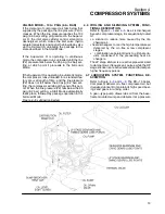
The lube oil is sequentially pumped through a heat
exchanger, the first and second stage compressor
cooling jackets, a high efficiency, replaceable ele-
ment filter, and a multiport manifold, where the fil-
tered outflow is distributed to bearing and gear lu-
brication points on the compressor and the gear
box. Filtered oil is also used to actuate the hydro
actuator linked to the inlet control valve.
The Supervisor
II
senses and displays the filter out-
let pressure and temperature. As a safety mea-
sure, unless oil pressure builds up to 25 psig (1.7
bar) within 10 seconds after startup, the Supervisor
II
shuts down the unit. In addition, if the pressure
drop across the filter ports exceeds 10 psig (6.9
bar), the Supervisor
II
displays a maintenance re-
quirement message.
All lubed points return the oil to the sump by gravity.
Vents on the compressor timing gear covers and
the gear box are also piped into the sump, to avoid
releasing oil vapor. The sump is vented to atmo-
sphere via a breather which includes an oil vapor
trap.
4.8 BUFFER AIR SYSTEM, FUNCTIONAL DE-
SCRIPTION
A small supply of cooled, compressed air is taken
at the aftercooler moisture separator, and used to
feed the buffer air system. This compressed air
goes through a control air filter, and then through a
pressure regulator, where the pressure is reduced
from the compressor operating pressure to 12 psig
(0.08 bar) (read from locally---mounted pressure
gauge). This clean, compressed air supply is fed to
both first and second compression stages. This air
provides a positive pressure buffer to the seals be-
tween the compression air and oil sides of the
stages, assuring oil---free air. The buffer air is then
drained from the stages, manifolded together, and
piped to the exterior of the package.
Summary of Contents for DR-13 Series
Page 6: ...NOTES ...
Page 14: ...8 NOTES ...
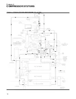
Page 18: ...Section 4 COMPRESSOR SYSTEMS 12 Figure 4 5 Piping and Instrumentation Diagram Air cooled ...
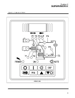
Page 21: ...Section 5 SUPERVISOR II 15 Figure 5 1 Supervisor II Panel ...
Page 28: ...22 NOTES ...
Page 32: ...26 NOTES ...
Page 42: ...Section 7 MAINTENANCE 36 Table 1 Installation Data ...
Page 46: ...40 NOTES ...
Page 48: ...Section 9 ILLUSTRATIONS AND PARTS LIST 42 9 3 COMPRESSOR MOTOR AND FRAME ...
Page 50: ...Section 9 ILLUSTRATIONS AND PARTS LIST 44 9 4 AIR INLET SYSTEM ...
Page 52: ...Section 9 ILLUSTRATIONS AND PARTS LIST 46 9 5 COOLER ASSEMBLY ...
Page 54: ...Section 9 ILLUSTRATIONS AND PARTS LIST 48 9 6 LP HOT LP COLD ...
Page 56: ...Section 9 ILLUSTRATIONS AND PARTS LIST 50 9 7 HP DISCHARGE ...
Page 58: ...Section 9 ILLUSTRATIONS AND PARTS LIST 52 9 8 LUBE SYSTEM ...
Page 60: ...Section 9 ILLUSTRATIONS AND PARTS LIST 54 9 9 ELECTRICAL BOX ...
Page 62: ...Section 9 ILLUSTRATIONS AND PARTS LIST 56 9 10 CONTROL SYSTEM CONDENSATE DRAIN ...
Page 64: ...Section 9 ILLUSTRATIONS AND PARTS LIST 58 9 11 CANOPY ...
Page 66: ...Section 9 ILLUSTRATIONS AND PARTS LIST 60 9 12 DECALS ...
Page 68: ...Section 9 ILLUSTRATIONS AND PARTS LIST 62 9 12 DECALS ...
Page 70: ...Section 9 ILLUSTRATIONS AND PARTS LIST 64 9 12 DECALS ...
Page 72: ...Section 9 ILLUSTRATIONS AND PARTS LIST 66 9 13 DECAL LOCATIONS ...
Page 74: ...Section 9 ILLUSTRATIONS AND PARTS LIST 68 9 13 DECAL LOCATIONS ...
Page 76: ...Section 9 ILLUSTRATIONS AND PARTS LIST 70 9 13 DECAL LOCATIONS ...
Page 78: ...Section 9 ILLUSTRATIONS AND PARTS LIST 72 9 14 WIRING DIAGRAM ...
Page 79: ...NOTES ...


