Section 1
SAFETY
1
1.1 GENERAL
Sullair Corporation and its subsidiaries designs
and manufactures all of its products so they can be
operated safely. However, the responsibility for
safe operation rests with those who use and main-
tain these products. The following safety precau-
tions are offered as a guide which, if conscien-
tiously followed, will minimize the possibility of acci-
dents throughout the useful life of this equipment.
The compressor should be operated only by those
who have been trained and delegated to do so, and
who have read and understood this Operator’s
Manual. Failure to follow the instructions, proce-
dures and safety precautions in this manual may
result in accidents and injuries.
NEVER
start the compressor unless it is safe to do
so.
DO NOT
attempt to operate the compressor
with a known unsafe condition. Tag the compres-
sor and render it inoperative by disconnecting and
locking out all power at source or otherwise dis-
abling its prime mover so others who may not know
of the unsafe condition cannot attempt to operate it
until the condition is corrected.
Install, use and operate the compressor only in full
compliance with all pertinent OSHA regulations
and/or any applicable Federal, State, and Local
codes, standards and regulations.
DO NOT
modify the compressor and/or controls in
any way except with written factory approval.
While not specifically applicable to all types of com-
pressors with all types of prime movers, most of the
precautionary statements contained herein are ap-
plicable to most compressors and the concepts
behind these statements are generally applicable
to all compressors.
1.2 PERSONAL PROTECTIVE EQUIPMENT
Prior to installing or operating the compressor,
owners, employers and users should become fa-
miliar with, and comply with, all applicable OSHA
regulations and/or any applicable Federal, State
and Local codes, standards, and regulations rela-
tive to personal protective equipment, such as eye
and face protective equipment, respiratory protec-
tive equipment, equipment intended to protect the
extremities, protective clothing, protective shields
and barriers and electrical protective equipment,
as well as noise exposure administrative and/or en-
gineering controls and/or personal hearing protec-
tive equipment.
1.3 PRESSURE RELEASE
A.
Install an appropriate flow---limiting valve be-
tween the service air outlet and the shut---off (throt-
tle) valve, either at the compressor or at any other
point along the air line, when an air hose exceeding
1/2” (13mm) inside diameter is to be connected to
the shut---off (throttle) valve, to reduce pressure in
case of hose failure, per OSHA Standard 29 CFR
1926.302(b)(7) and/or any applicable Federal,
State and Local codes, standards and regulations.
B.
When the hose is to be used to supply a mani-
fold, install an additional appropriate flow---limiting
valve between the manifold and each air hose ex-
ceeding 1/2” (13mm) inside diameter that is to be
connected to the manifold to reduce pressure in
case of hose failure.
C.
Provide an appropriate flow---limiting valve at the
beginning of each additional 75 feet (23m) of hose
in runs of air hose exceeding 1/2” (13mm) inside di-
ameter to reduce pressure in case of hose failure.
D.
Flow---limiting valves are listed by pipe size and
rated CFM. Select appropriate valves accordingly,
in accordance with their manufacturer’s recom-
mendations.
E. DO NOT
use air tools that are rated below the
maximum rating of the compressor. Select air tools,
air hoses, pipes, valves, filters and other fittings ac-
cordingly.
DO NOT
exceed manufacturer’s rated
safe operating pressures for these items.
F.
Secure all hose connections by wire, chain or
other suitable retaining device to prevent tools or
hose ends from being accidentally disconnected
and expelled.
G.
Open fluid filler cap only when compressor
is
not running and is not pressurized.
Shut down
the compressor and bleed the sump to zero inter-
nal pressure before removing the cap.
H.
Vent all internal pressure prior to opening any
line, fitting, hose, valve, drain plug, connection or
other component, such as filters and line oilers,
and before attempting to refill optional air line anti---
icer systems with antifreeze compound.
I.
Keep personnel out of line with and away from the
discharge opening of hoses or tools or other points
of compressed air discharge.
J.
Use air at pressures less than 30 psig (2.1 barg)
for cleaning purposes, and then only with effective
chip guarding and personal protective equipment
per OSHA Standard 29 CFR 1910.242 (b) and/or
any applicable Federal, State, and Local codes,
standards and regulations.
K. DO NOT
engage in horseplay with air hoses as
death or serious injury may result.
1.4 FIRE AND EXPLOSION
A.
Clean up spills of lubricant or other combustible
substances immediately, if such spills occur.
B.
Shut off the compressor and allow it to cool.
Then keep sparks, flames and other sources of ig-
nition away and
DO NOT
permit smoking in the vi-
cinity when checking or adding lubricant or when
refilling air line anti---icer systems with antifreeze
compound.
Summary of Contents for DR-13 Series
Page 6: ...NOTES ...
Page 14: ...8 NOTES ...
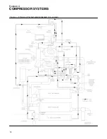
Page 18: ...Section 4 COMPRESSOR SYSTEMS 12 Figure 4 5 Piping and Instrumentation Diagram Air cooled ...
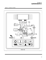
Page 21: ...Section 5 SUPERVISOR II 15 Figure 5 1 Supervisor II Panel ...
Page 28: ...22 NOTES ...
Page 32: ...26 NOTES ...
Page 42: ...Section 7 MAINTENANCE 36 Table 1 Installation Data ...
Page 46: ...40 NOTES ...
Page 48: ...Section 9 ILLUSTRATIONS AND PARTS LIST 42 9 3 COMPRESSOR MOTOR AND FRAME ...
Page 50: ...Section 9 ILLUSTRATIONS AND PARTS LIST 44 9 4 AIR INLET SYSTEM ...
Page 52: ...Section 9 ILLUSTRATIONS AND PARTS LIST 46 9 5 COOLER ASSEMBLY ...
Page 54: ...Section 9 ILLUSTRATIONS AND PARTS LIST 48 9 6 LP HOT LP COLD ...
Page 56: ...Section 9 ILLUSTRATIONS AND PARTS LIST 50 9 7 HP DISCHARGE ...
Page 58: ...Section 9 ILLUSTRATIONS AND PARTS LIST 52 9 8 LUBE SYSTEM ...
Page 60: ...Section 9 ILLUSTRATIONS AND PARTS LIST 54 9 9 ELECTRICAL BOX ...
Page 62: ...Section 9 ILLUSTRATIONS AND PARTS LIST 56 9 10 CONTROL SYSTEM CONDENSATE DRAIN ...
Page 64: ...Section 9 ILLUSTRATIONS AND PARTS LIST 58 9 11 CANOPY ...
Page 66: ...Section 9 ILLUSTRATIONS AND PARTS LIST 60 9 12 DECALS ...
Page 68: ...Section 9 ILLUSTRATIONS AND PARTS LIST 62 9 12 DECALS ...
Page 70: ...Section 9 ILLUSTRATIONS AND PARTS LIST 64 9 12 DECALS ...
Page 72: ...Section 9 ILLUSTRATIONS AND PARTS LIST 66 9 13 DECAL LOCATIONS ...
Page 74: ...Section 9 ILLUSTRATIONS AND PARTS LIST 68 9 13 DECAL LOCATIONS ...
Page 76: ...Section 9 ILLUSTRATIONS AND PARTS LIST 70 9 13 DECAL LOCATIONS ...
Page 78: ...Section 9 ILLUSTRATIONS AND PARTS LIST 72 9 14 WIRING DIAGRAM ...
Page 79: ...NOTES ...


