Section 2
DESCRIPTION
7
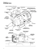
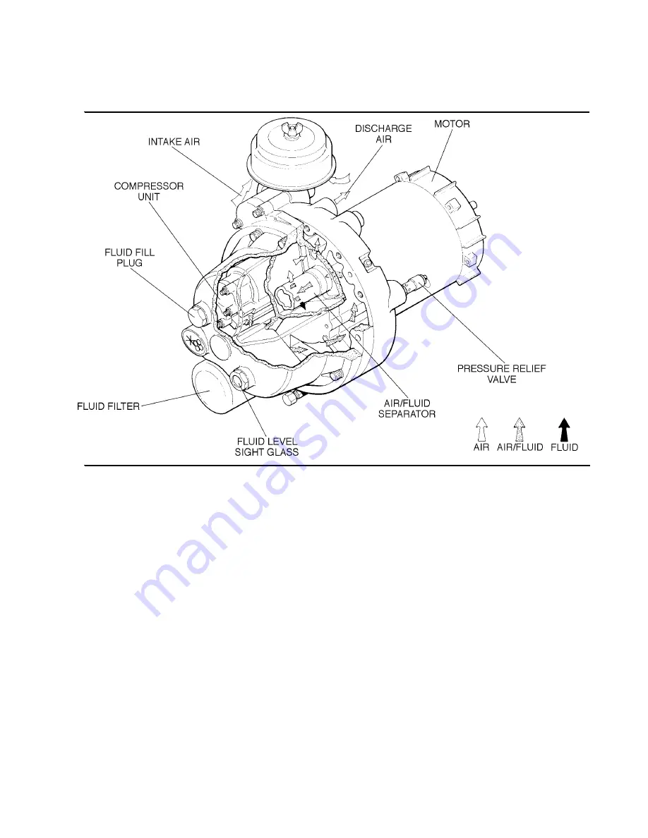
Figure 2--2 Encapsulated Compressor System
2.6 CONTROL SYSTEM, FUNCTIONAL DE-
SCRIPTION
The purpose of the compressor control system is to
maintain compressor capacity to meet the system
demand.
It consists of an
inlet valve, solenoid valve, con-
trol lines
and the
motor start selector switch
.
The selector switch has three settings:
MANUAL/
START
,
OFF/RESET
and
AUTOMATIC START/
STOP
.
MANUAL MODE
The compressor motor will start and the air control
solenoid valve will be energized. The compressor
will start to deliver compressed air. When no air is
being used, the service line pressure rises to the
setting (cut--out pressure) of the pressure switch.
The system pressure switch opens, interrupting the
electrical power to the solenoid valve. The solenoid
valve allows control air to the inlet valve, unloading
the compressor and the motor continues to run.
When the line pressure drops to the low setting of
the pressure switch, the pressure switch closes, re--
energizing the normally open solenoid valve and al-
lowing the compressor to load again.
OFF/RESET MODE
The compressor motor, if running, will stop if the off/
reset position is selected. If the compressor during
normal running has a fault caused by either overload
or high discharge temperature, the compressor will
stop. After a fault has been cleared, the compressor
can not be restarted unless the Off/Reset mode is
selected on the selector switch, prior to starting in
any other mode of operation.
AUTOMATIC MODE
In the automatic mode of operation, the air system
pressure switch opens, interrupting the electrical
power to the air control solenoid valve; the compres-
sor unloads and the motor will stop. The motor will
automatically restart when the compressor sump
pressure drops to the minimum setpoint on the
sump pressure switch and the line pressure drops
below the setpoint of the air pressure switch.
Summary of Contents for ES-6 series
Page 6: ...NOTES...
Page 30: ...Section 7 ILLUSTRATIONS AND PARTS LIST 24 ES 6 COMPRESSOR ASSEMBLY EXPLODED VIEW 5 5 AND 7 5KW...
Page 32: ...Section 7 ILLUSTRATIONS AND PARTS LIST 26 7 3 FLUID MANAGEMENT SYSTEM...
Page 34: ...Section 7 ILLUSTRATIONS AND PARTS LIST 28 7 4 INLET FILTER...
Page 36: ...Section 7 ILLUSTRATIONS AND PARTS LIST 30 7 5 SEAL AND DRIVE GEAR...
Page 38: ...Section 7 ILLUSTRATIONS AND PARTS LIST 32 7 6 MOTOR HOUSING AND PARTS 7 5 10HP 5 5 7 5KW ONLY...
Page 42: ...Section 7 ILLUSTRATIONS AND PARTS LIST 36 7 8 COMPRESSOR SYSTEM...
Page 44: ...Section 7 ILLUSTRATIONS AND PARTS LIST 38 7 9 INLET CONTROL...
Page 46: ...Section 7 ILLUSTRATIONS AND PARTS LIST 40 7 10 CONTROL BOX...
Page 48: ...Section 7 ILLUSTRATIONS AND PARTS LIST 42 7 10 CONTROL BOX...
Page 52: ...Section 7 ILLUSTRATIONS AND PARTS LIST 46 7 12 FRAME CANOPY AND PARTS...
Page 56: ...Section 7 ILLUSTRATIONS AND PARTS LIST 50 7 14 WYE DELTA ELECTRIC BOX ES 6...
Page 58: ...Section 7 ILLUSTRATIONS AND PARTS LIST 52 7 15 DECAL GROUP 7 8 9 11 12...
Page 60: ...Section 7 ILLUSTRATIONS AND PARTS LIST 54 7 15 DECAL GROUP 13...
Page 62: ...Section 7 ILLUSTRATIONS AND PARTS LIST 56 7 16 WIRING DIAGRAM SINGLE PHASE 60Hz...
Page 63: ...Section 7 ILLUSTRATIONS AND PARTS LIST 57 7 17 WIRING DIAGRAM THREE PHASE 60Hz...
Page 64: ...Section 7 ILLUSTRATIONS AND PARTS LIST 58 7 18 WIRING DIAGRAM 50 Hz...
Page 65: ...Section 7 ILLUSTRATIONS AND PARTS LIST 59 7 19 WIRING DIAGRAM 50 Hz WYE DELTA...
Page 66: ...NOTES...
Page 67: ...NOTES...


