Section 3
SPECIFICATIONS
10
AMBIENT
TEMPERATURE
LUBRICATION
FLUID CHANGE
PERIOD (HRS.)
FILTER CHANGE
PERIOD (HRS.)
--10
q
F to +90
q
F
(--23
q
C to +32
q
C)
Sullube 32
8000
*
8000
*
Sullair LLL--4--32
8000
*
8000
*
SRF 1/4000
4000
4000
D--A Torque Fluid
1000
1000
Motor Oil MIL--2104E
SPEC API SF CC,
CD SAE 10W Class SE
600
600
* 8,000 Hours or once a year.
Table 3--1, Lubrication Guide
3.2 COMPRESSOR LUBRICATION GUIDE
For best value and longest uninterrupted service,
the ES--6 compressor is factory filled with Sullube
32, a long life lubricant, unless a different lubricant is
requested.
If, due to availability or other reasons, other fluids
ar e r equir ed, f ollow
Lubr ic at ion G uide.
WARNING
!
“The Plastic Pipe Institute recommends against
the use of thermoplastic pipe to transport com-
pressed air or other compressed gases in exposed
above ground locations, e.g. in exposed plant pip-
ing.” (I)
Sullube 32 should not be used with PVC piping
systems. It may affect the bond at cemented joints.
Certain other plastic materials may also be af-
fected.
(I) Plastic Pipe Institute, Recommendation B,
Adopted January 19, 1972.
Maintenance of all other components is still recom-
mended as indicated in the Operator’s Manual.
For light--duty high--humidity service where con-
densed moisture and emulsification (mayonnaise)
may occur, the fluid change interval must be re-
duced to 300 hours maximum. A non--detergent
fluid with rust, oxidation and foam inhibitors and
good water separation characteristics should be
used.
DO NOT MIX DIFFERENT TYPES OF FLUIDS.
Contamination of non--detergent mineral fluids with
traces of ATF or detergent motor fluids may lead to
operational problems such as foaming, filter plug-
ging, orifice or line plugging. Flushing is required if
changing to a different lubricant.
WARNING
!
Mixing of other fluids within the compressor will
void all warranties.
When ambient conditions exceed those noted or if
conditions warrant use of “extended” life lubricants
contact Sullair for recommendation.
Sullair encourages the user to participate in a fluid
analysis program. This could result in a fluid change
interval that is different from those stated in this
manual.
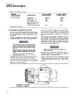
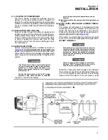
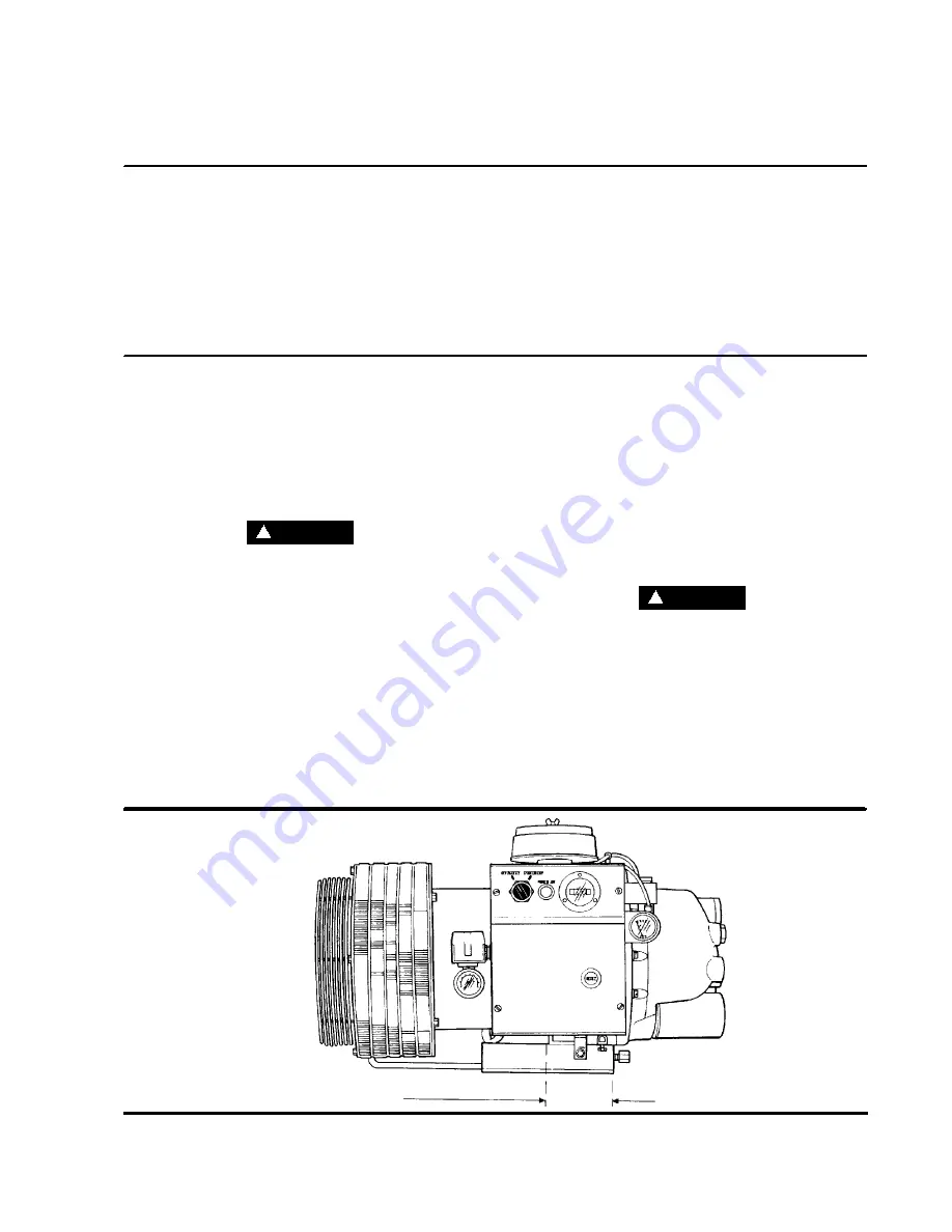
Figure 3--1 Center of Gravity
APPROX. 6” (15.2CM)
CENTER OF GRAVITY
Summary of Contents for ES-6 series
Page 6: ...NOTES...
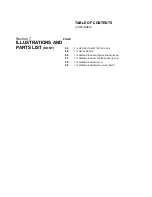
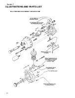
Page 30: ...Section 7 ILLUSTRATIONS AND PARTS LIST 24 ES 6 COMPRESSOR ASSEMBLY EXPLODED VIEW 5 5 AND 7 5KW...
Page 32: ...Section 7 ILLUSTRATIONS AND PARTS LIST 26 7 3 FLUID MANAGEMENT SYSTEM...
Page 34: ...Section 7 ILLUSTRATIONS AND PARTS LIST 28 7 4 INLET FILTER...
Page 36: ...Section 7 ILLUSTRATIONS AND PARTS LIST 30 7 5 SEAL AND DRIVE GEAR...
Page 38: ...Section 7 ILLUSTRATIONS AND PARTS LIST 32 7 6 MOTOR HOUSING AND PARTS 7 5 10HP 5 5 7 5KW ONLY...
Page 42: ...Section 7 ILLUSTRATIONS AND PARTS LIST 36 7 8 COMPRESSOR SYSTEM...
Page 44: ...Section 7 ILLUSTRATIONS AND PARTS LIST 38 7 9 INLET CONTROL...
Page 46: ...Section 7 ILLUSTRATIONS AND PARTS LIST 40 7 10 CONTROL BOX...
Page 48: ...Section 7 ILLUSTRATIONS AND PARTS LIST 42 7 10 CONTROL BOX...
Page 52: ...Section 7 ILLUSTRATIONS AND PARTS LIST 46 7 12 FRAME CANOPY AND PARTS...
Page 56: ...Section 7 ILLUSTRATIONS AND PARTS LIST 50 7 14 WYE DELTA ELECTRIC BOX ES 6...
Page 58: ...Section 7 ILLUSTRATIONS AND PARTS LIST 52 7 15 DECAL GROUP 7 8 9 11 12...
Page 60: ...Section 7 ILLUSTRATIONS AND PARTS LIST 54 7 15 DECAL GROUP 13...
Page 62: ...Section 7 ILLUSTRATIONS AND PARTS LIST 56 7 16 WIRING DIAGRAM SINGLE PHASE 60Hz...
Page 63: ...Section 7 ILLUSTRATIONS AND PARTS LIST 57 7 17 WIRING DIAGRAM THREE PHASE 60Hz...
Page 64: ...Section 7 ILLUSTRATIONS AND PARTS LIST 58 7 18 WIRING DIAGRAM 50 Hz...
Page 65: ...Section 7 ILLUSTRATIONS AND PARTS LIST 59 7 19 WIRING DIAGRAM 50 Hz WYE DELTA...
Page 66: ...NOTES...
Page 67: ...NOTES...


