Section 4
INSTALLATION
12
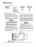
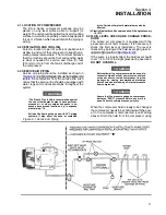
t he c om pr es s or f luid dr ain c ap ( S ee
) .
Fluid capacity for the compressor can be found in
Section 3, Specifications of this manual. The com-
pressor sump is properly filled when the level on the
fluid level sight tube is 3/4 of the sight tube. During
operation, the fluid level should cover 1/4 to 1/2 of
the sight glass.
DO NOT OVERFILL.
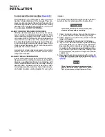
4.5 MOTOR ROTATION DIRECTION CHECK
After the electrical wiring has been done, it is neces-
sary to check the direction of motor rotation. This
can be done by jogging the START selector switch
on the side of the control center. When looking at the
motor from the cooler end of the compressor unit,
the cooler fan should be turning clockwise. If the mo-
tor is not turning clockwise, disconnect power to the
starter and exchange any two of the three power in-
put leads, then check rotation.
A direction of rotation decal is located on the motor
shroud, next to the cooler to insure correct motor/
compressor rotation.
4.6 ELECTRICAL PREPARATION
Interior electrical wiring is performed at the factory.
Required customer wiring is minimal, but should be
done by a qualified electrician in compliance with
OSHA, National Electrical Code, and any other ap-
plicable State, Federal and local electrical codes
concerning isolation switches, fused disconnects,
etc. Sullair provides a wiring diagram for use by the
installer.
A few electrical checks should be made to help as-
sure that the first start--up will be trouble--free.
WARNING
!
Lethal shock hazard inside. Disconnect all power
at source before opening or servicing.
1. Check incoming voltage. Be sure that compres-
sor is wired for the correct incoming voltage.
2. Check starter for correct size, proper overload
relay and heaters.
3. Check all electrical connections for tightness.
4. “Dry run” the electrical controls by disconnecting
the motor leads T1, T2, and T3 from the starter.
Energize the control circuits by turning the selec-
tor switch to the manual and automatic positions,
and check all protection devices making sure
when activated, they will de--energize the starter
control coil.
5. Reconnect the motor leads and jog the motor for
a dir ec t ion of r ot at ion c hec k as ex plained in
NOTE
Wiring diagram for standard compressors is sup-
plied on the inside cover of the Control Center.
Optional compressor wiring diagrams will vary.
Summary of Contents for ES-6 series
Page 6: ...NOTES...
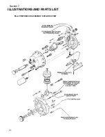
Page 30: ...Section 7 ILLUSTRATIONS AND PARTS LIST 24 ES 6 COMPRESSOR ASSEMBLY EXPLODED VIEW 5 5 AND 7 5KW...
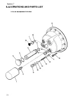
Page 32: ...Section 7 ILLUSTRATIONS AND PARTS LIST 26 7 3 FLUID MANAGEMENT SYSTEM...
Page 34: ...Section 7 ILLUSTRATIONS AND PARTS LIST 28 7 4 INLET FILTER...
Page 36: ...Section 7 ILLUSTRATIONS AND PARTS LIST 30 7 5 SEAL AND DRIVE GEAR...
Page 38: ...Section 7 ILLUSTRATIONS AND PARTS LIST 32 7 6 MOTOR HOUSING AND PARTS 7 5 10HP 5 5 7 5KW ONLY...
Page 42: ...Section 7 ILLUSTRATIONS AND PARTS LIST 36 7 8 COMPRESSOR SYSTEM...
Page 44: ...Section 7 ILLUSTRATIONS AND PARTS LIST 38 7 9 INLET CONTROL...
Page 46: ...Section 7 ILLUSTRATIONS AND PARTS LIST 40 7 10 CONTROL BOX...
Page 48: ...Section 7 ILLUSTRATIONS AND PARTS LIST 42 7 10 CONTROL BOX...
Page 52: ...Section 7 ILLUSTRATIONS AND PARTS LIST 46 7 12 FRAME CANOPY AND PARTS...
Page 56: ...Section 7 ILLUSTRATIONS AND PARTS LIST 50 7 14 WYE DELTA ELECTRIC BOX ES 6...
Page 58: ...Section 7 ILLUSTRATIONS AND PARTS LIST 52 7 15 DECAL GROUP 7 8 9 11 12...
Page 60: ...Section 7 ILLUSTRATIONS AND PARTS LIST 54 7 15 DECAL GROUP 13...
Page 62: ...Section 7 ILLUSTRATIONS AND PARTS LIST 56 7 16 WIRING DIAGRAM SINGLE PHASE 60Hz...
Page 63: ...Section 7 ILLUSTRATIONS AND PARTS LIST 57 7 17 WIRING DIAGRAM THREE PHASE 60Hz...
Page 64: ...Section 7 ILLUSTRATIONS AND PARTS LIST 58 7 18 WIRING DIAGRAM 50 Hz...
Page 65: ...Section 7 ILLUSTRATIONS AND PARTS LIST 59 7 19 WIRING DIAGRAM 50 Hz WYE DELTA...
Page 66: ...NOTES...
Page 67: ...NOTES...

