Section 6
MAINTENANCE
18
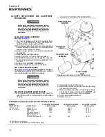
Figure 6--4 Minimum Pressure/Check Valve
(P/N 606058)
* Repair Kit P/N 250030--226
5. Reinstall the cap. Hand--tighten using a 4” maxi-
mum length, 1/4” diameter pin in the radially
drilled hole.
MINIMUM PRESSURE/CHECK VALVE MAINTE-
NANCE
. M inim um pr es s ur e/ c hec k v alv e
maintenance is minimal. The only parts which nor-
mally require replacement are the o--ring seal
around the piston and the valve seat on the check
valve. To replace any of the two parts, follow the pro-
cedure explained below.
WARNING
!
Before doing compressor maintenance, discon-
nect compressor from power source and lock out
power source. Isolate compressor from line pres-
sure by closing recommended discharge shut--
off valve and releasing all internal pressure from
compressor.
WARNING
!
Assure that line pressure gauge on compressor
indicates “ZERO” pressure before any work is
done. Failure to comply can cause injury.
1. Unscrew the minimum pressure valve from the
drive housing.
2. Remove all parts.
3. Clean and inspect all parts.
4. Remove the screw holding the check valve seat.
Replace valve seat. Reinstall securing with Loc-
titeR #222.
5. Install new o--ring. Before reinstallation, lubricate
with Parker Super “O” ring seal or an equivalent
grease.
6. Reinstall the whole valve assembly. Tighten and
secure.
THERMOSTAT ACTUATOR MAINTENANCE
. T he only par t whic h would ev er
need replacement is the thermostat valve actuator.
For replacement, follow the procedure explained
below.
WARNING
!
Before doing compressor maintenance, discon-
nect compressor from power source and lock out
power source. Isolate compressor from line pres-
sure by closing recommended discharge shut--
off valve and releasing all internal pressure from
compressor.
1. To prevent spillage and loss of re--usable fluid,
place a contaminate--free fluid receptacle be-
neath fluid drain valve and fluid filter.
2. Drain fluid by removing fluid drain cap at tee lo-
cated beneath compressor.
3. Unscrew and remove hollow hex plug.
4. Remove spring and piston.
5. By using long nosed pliers, pull the actuator out.
6. Install new actuator.
7. Install piston and spring with centering guide.
8. Re--install plug.
Figure 6--5 Thermostat Actuator(P/N 250025--413)
* Repair Kit P/N 250028--036
Summary of Contents for ES-6 series
Page 6: ...NOTES...
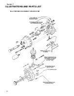
Page 30: ...Section 7 ILLUSTRATIONS AND PARTS LIST 24 ES 6 COMPRESSOR ASSEMBLY EXPLODED VIEW 5 5 AND 7 5KW...
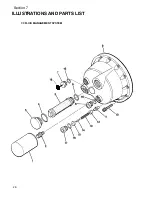
Page 32: ...Section 7 ILLUSTRATIONS AND PARTS LIST 26 7 3 FLUID MANAGEMENT SYSTEM...
Page 34: ...Section 7 ILLUSTRATIONS AND PARTS LIST 28 7 4 INLET FILTER...
Page 36: ...Section 7 ILLUSTRATIONS AND PARTS LIST 30 7 5 SEAL AND DRIVE GEAR...
Page 38: ...Section 7 ILLUSTRATIONS AND PARTS LIST 32 7 6 MOTOR HOUSING AND PARTS 7 5 10HP 5 5 7 5KW ONLY...
Page 42: ...Section 7 ILLUSTRATIONS AND PARTS LIST 36 7 8 COMPRESSOR SYSTEM...
Page 44: ...Section 7 ILLUSTRATIONS AND PARTS LIST 38 7 9 INLET CONTROL...
Page 46: ...Section 7 ILLUSTRATIONS AND PARTS LIST 40 7 10 CONTROL BOX...
Page 48: ...Section 7 ILLUSTRATIONS AND PARTS LIST 42 7 10 CONTROL BOX...
Page 52: ...Section 7 ILLUSTRATIONS AND PARTS LIST 46 7 12 FRAME CANOPY AND PARTS...
Page 56: ...Section 7 ILLUSTRATIONS AND PARTS LIST 50 7 14 WYE DELTA ELECTRIC BOX ES 6...
Page 58: ...Section 7 ILLUSTRATIONS AND PARTS LIST 52 7 15 DECAL GROUP 7 8 9 11 12...
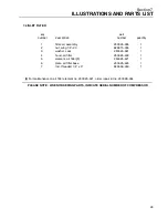
Page 60: ...Section 7 ILLUSTRATIONS AND PARTS LIST 54 7 15 DECAL GROUP 13...
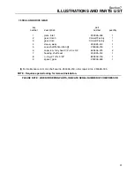
Page 62: ...Section 7 ILLUSTRATIONS AND PARTS LIST 56 7 16 WIRING DIAGRAM SINGLE PHASE 60Hz...
Page 63: ...Section 7 ILLUSTRATIONS AND PARTS LIST 57 7 17 WIRING DIAGRAM THREE PHASE 60Hz...
Page 64: ...Section 7 ILLUSTRATIONS AND PARTS LIST 58 7 18 WIRING DIAGRAM 50 Hz...
Page 65: ...Section 7 ILLUSTRATIONS AND PARTS LIST 59 7 19 WIRING DIAGRAM 50 Hz WYE DELTA...
Page 66: ...NOTES...
Page 67: ...NOTES...

