Section 6
MAINTENANCE
19
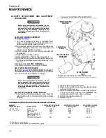
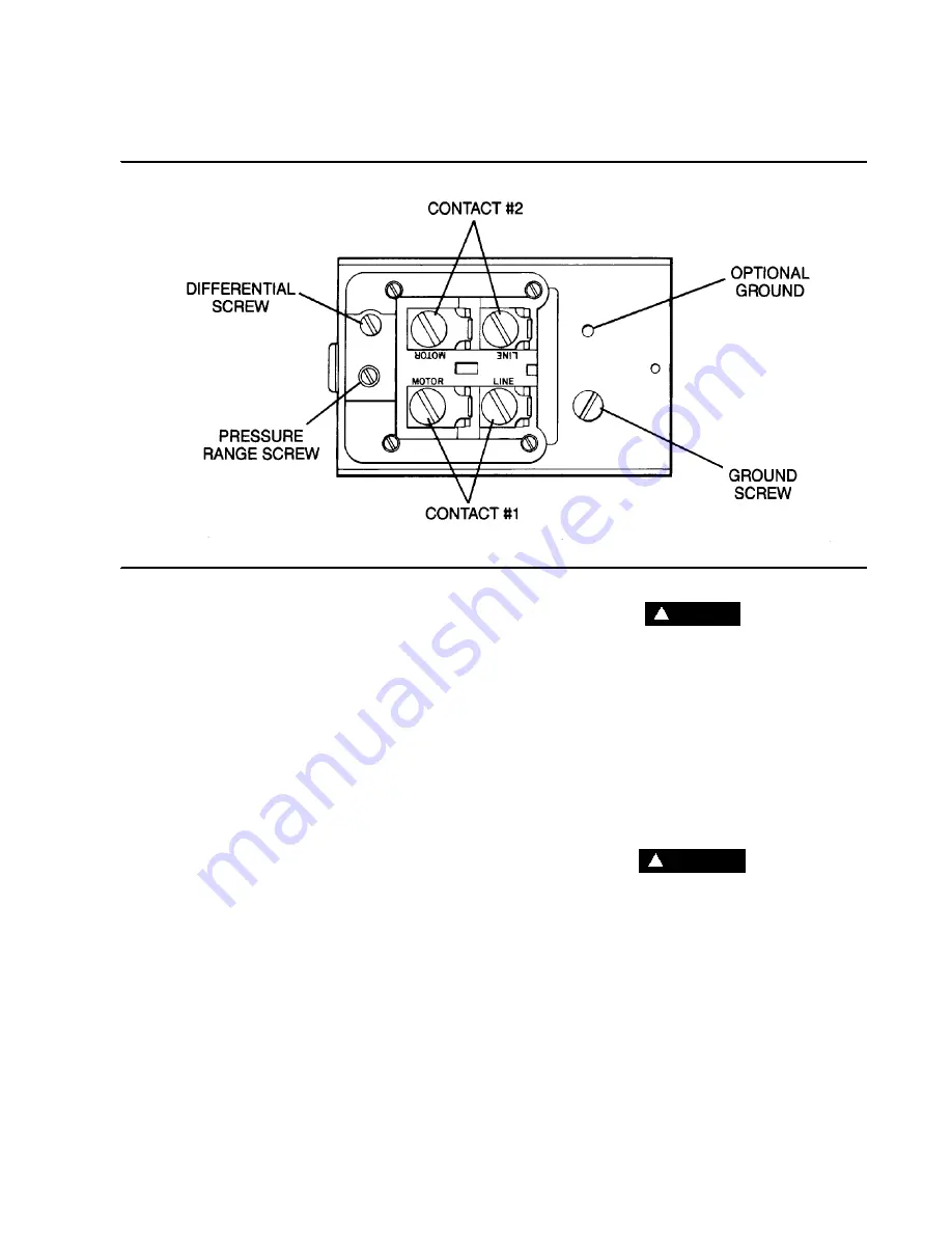
Figure 6--6 Air Pressure Switch (P/N 250025--299)
CONTROL SYSTEM ADJUSTMENT
. A ll c om ponent s in t he Cont r ol
System are designed and manufactured to close tol-
erances to eliminate any need for adjustments. The
only adjustment required is to set the air pressure
switch. This is done by following the instructions be-
low.
1. Remove the pressure switch cover.
2. With the shut--off valve closed or slightly cracked
open, start the compressor.
3. Observe the line pressure gauge and pressure
switch contacts. When the line pressure reaches
nameplate pressure, the pressure switch con-
tacts should open.
4. If the pressure switch contacts do not open or
they open prior to the desired pressure, the pres-
sure switch setting will require adjustment (refer
to Figure 6--6). To adjust the pressure switch,
turn the range--adjusting screw to the high pres-
sure setting. Turning the screw counterclockwise
lowers both the high and low pressure setting
equally.
FOR DIFFERENTIAL ADJUSTMENT OF AIR
PRESSURE SWITCH:
Differential is the difference between the high and
low pressure settings.
Turning the screw clockwise increases the differen-
tial, and counterclockwise decreases the differential
pressure.
DANGER
!
DO NOT touch the electrical contacts, terminal or
leads with any part of the body or any uninsulated
metallic object. Severe electrical shock may oc-
cur.
UNLOADER SOLENOID VALVE MAINTENANCE
Unloader valve maintenance is minimal, but a peri-
odic cleaning is desirable. The time between clean-
ings will vary depending on operating conditions. In
general, if the voltage to the coils is correct, sluggish
valve operation or excessive leakage will indicate
that cleaning is required.
WARNING
!
Turn off all power, relieve sump pressure, and dis-
connect coil lead wires to the solenoid valve be-
fore making repairs.
It is not necessary to remove the valve from the pipe
line for repairs.
DISASSEMBLY AND REASSEMBLY
1. Remove the retaining cap and slip the entire sole-
noid off the solenoid base subassembly.
2. Unscrew the solenoid base assembly. Remove
the core assembly, core spring and body gasket.
3. All parts are now accessible for cleaning or re-
placement.
4. Reassemble in reverse order of disassembly.
Summary of Contents for ES-6 series
Page 6: ...NOTES...
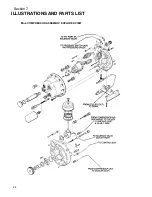
Page 30: ...Section 7 ILLUSTRATIONS AND PARTS LIST 24 ES 6 COMPRESSOR ASSEMBLY EXPLODED VIEW 5 5 AND 7 5KW...
Page 32: ...Section 7 ILLUSTRATIONS AND PARTS LIST 26 7 3 FLUID MANAGEMENT SYSTEM...
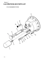
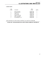
Page 34: ...Section 7 ILLUSTRATIONS AND PARTS LIST 28 7 4 INLET FILTER...
Page 36: ...Section 7 ILLUSTRATIONS AND PARTS LIST 30 7 5 SEAL AND DRIVE GEAR...
Page 38: ...Section 7 ILLUSTRATIONS AND PARTS LIST 32 7 6 MOTOR HOUSING AND PARTS 7 5 10HP 5 5 7 5KW ONLY...
Page 42: ...Section 7 ILLUSTRATIONS AND PARTS LIST 36 7 8 COMPRESSOR SYSTEM...
Page 44: ...Section 7 ILLUSTRATIONS AND PARTS LIST 38 7 9 INLET CONTROL...
Page 46: ...Section 7 ILLUSTRATIONS AND PARTS LIST 40 7 10 CONTROL BOX...
Page 48: ...Section 7 ILLUSTRATIONS AND PARTS LIST 42 7 10 CONTROL BOX...
Page 52: ...Section 7 ILLUSTRATIONS AND PARTS LIST 46 7 12 FRAME CANOPY AND PARTS...
Page 56: ...Section 7 ILLUSTRATIONS AND PARTS LIST 50 7 14 WYE DELTA ELECTRIC BOX ES 6...
Page 58: ...Section 7 ILLUSTRATIONS AND PARTS LIST 52 7 15 DECAL GROUP 7 8 9 11 12...
Page 60: ...Section 7 ILLUSTRATIONS AND PARTS LIST 54 7 15 DECAL GROUP 13...
Page 62: ...Section 7 ILLUSTRATIONS AND PARTS LIST 56 7 16 WIRING DIAGRAM SINGLE PHASE 60Hz...
Page 63: ...Section 7 ILLUSTRATIONS AND PARTS LIST 57 7 17 WIRING DIAGRAM THREE PHASE 60Hz...
Page 64: ...Section 7 ILLUSTRATIONS AND PARTS LIST 58 7 18 WIRING DIAGRAM 50 Hz...
Page 65: ...Section 7 ILLUSTRATIONS AND PARTS LIST 59 7 19 WIRING DIAGRAM 50 Hz WYE DELTA...
Page 66: ...NOTES...
Page 67: ...NOTES...


