Section 6
MAINTENANCE
22
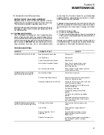
TROUBLESHOOTING
SYMPTOM
PROBABLE CAUSE
REMEDY
LI N E P R E S S U R E R I S E S A B O V E D ef ec t iv e S olenoid Valv e R epair s olenoid v alv e ( s ee
) .
CUT--OUT PRESSURE SETTING
ON PRESSURE SWITCH
Leak In Control System Causing
Check for leaks.
Loss Of Pressure Signals
Defective Pressure Switch
Check that diaphragm and contacts are not
damaged. Replace if necessary.
Inlet Valve Stuck Open
Inspect inlet valve and insure free operation
EXCESSIVE COMPRESSOR
Clogged Return Line
Remove element cover and clean orifice.
FLUID CONSUMPTION
Separator Element Damaged Or
Change separator element.
Not Functioning Properly
Leak In The Lubrication System
Check all pipes, connections and
components.
Excess Fluid Foaming
Drain and change.
Fluid Level Too High
Drain excess.
Shaft Seal Failure
Replace shaft seal.
PRESSURE RELIEF VALVE
Compressor Operating Pressure
See Symptom “Line Pressure Rises Above
OPENS REPEATEDLY
Too High
Cut--out Pressure Setting on Pressure
Switch” above
Defective Pressure Relief Valve
Replace pressure relief valve.
LIQUID WATER IN COMPRESSED
Water Vapor Condensation From Cooling
Remove the water vapor from compressed air prior
AIR LINES
and Compression Occurs Naturally
to distribution through the air system. Check
operation of aftercooler and moisture separator.
Install a compressed air dryer sized for the flow and
dryness level required. (Note: Filters may also be
required to remove particulates, liquid oil aerosols
or for oil vapor removal. Change cartridges as
recommended by the filter manufacturer.) Check all
drain traps routinely to insure their proper
operation. Maintain them regularly.
Summary of Contents for ES-6 series
Page 6: ...NOTES...
Page 30: ...Section 7 ILLUSTRATIONS AND PARTS LIST 24 ES 6 COMPRESSOR ASSEMBLY EXPLODED VIEW 5 5 AND 7 5KW...
Page 32: ...Section 7 ILLUSTRATIONS AND PARTS LIST 26 7 3 FLUID MANAGEMENT SYSTEM...
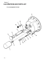
Page 34: ...Section 7 ILLUSTRATIONS AND PARTS LIST 28 7 4 INLET FILTER...
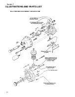
Page 36: ...Section 7 ILLUSTRATIONS AND PARTS LIST 30 7 5 SEAL AND DRIVE GEAR...
Page 38: ...Section 7 ILLUSTRATIONS AND PARTS LIST 32 7 6 MOTOR HOUSING AND PARTS 7 5 10HP 5 5 7 5KW ONLY...
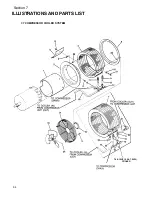
Page 42: ...Section 7 ILLUSTRATIONS AND PARTS LIST 36 7 8 COMPRESSOR SYSTEM...
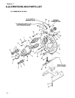
Page 44: ...Section 7 ILLUSTRATIONS AND PARTS LIST 38 7 9 INLET CONTROL...
Page 46: ...Section 7 ILLUSTRATIONS AND PARTS LIST 40 7 10 CONTROL BOX...
Page 48: ...Section 7 ILLUSTRATIONS AND PARTS LIST 42 7 10 CONTROL BOX...
Page 52: ...Section 7 ILLUSTRATIONS AND PARTS LIST 46 7 12 FRAME CANOPY AND PARTS...
Page 56: ...Section 7 ILLUSTRATIONS AND PARTS LIST 50 7 14 WYE DELTA ELECTRIC BOX ES 6...
Page 58: ...Section 7 ILLUSTRATIONS AND PARTS LIST 52 7 15 DECAL GROUP 7 8 9 11 12...
Page 60: ...Section 7 ILLUSTRATIONS AND PARTS LIST 54 7 15 DECAL GROUP 13...
Page 62: ...Section 7 ILLUSTRATIONS AND PARTS LIST 56 7 16 WIRING DIAGRAM SINGLE PHASE 60Hz...
Page 63: ...Section 7 ILLUSTRATIONS AND PARTS LIST 57 7 17 WIRING DIAGRAM THREE PHASE 60Hz...
Page 64: ...Section 7 ILLUSTRATIONS AND PARTS LIST 58 7 18 WIRING DIAGRAM 50 Hz...
Page 65: ...Section 7 ILLUSTRATIONS AND PARTS LIST 59 7 19 WIRING DIAGRAM 50 Hz WYE DELTA...
Page 66: ...NOTES...
Page 67: ...NOTES...

