Section 7
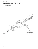
ILLUSTRATIONS AND PARTS LIST
25
7.1 PROCEDURE FOR ORDERING PARTS
Parts should be ordered from the nearest Sullair Representative or the Representative from whom the com-
pressor was purchased. If for any reason parts cannot be obtained in this manner, contact the factory directly at
the address, phone numbers or fax numbers below.
When ordering parts always indicate the
Serial Number
of the compressor. This can be obtained from the Bill of
Lading for the compressor or from the Serial Number Plate located on the compressor.
The genuine Sullair service parts listed meet or exceed the demands of this compressor. Use of replacement
parts other than those approved by Sullair Corporation may lead to hazardous conditions over which Sullair
Corporation has no control. Such conditions include, but are not limited to, bodily injury and compressor failure.
SULLAIR CORPORATION
Subsidiary of Sundstrand Corporation
3700 East Michigan Boulevard
Michigan City, Indiana 46360 U.S.A.
Telephone: 1--800--SULLAIR (U.S. Only) or
Fax: (219) 874 -- 1273
SULLAIR EUROPE, S.A.
Chemin de Genas BP 639
69800 Saint Priest, France
Telephone: 33--72232425
Fax: 33 -- 78907168
Fax: (219) 874 -- 1835 (Parts)
Fax (219) 874 -- 1805 (Service)
1--219--879--5451
SULLAIR ASIA, LTD.
Chiwan Supply Base
Bldg A5--1 Chiwan
Shenzhen, Guangdong PRV.
P.R.C. Post Code 518068
Telephone: 755--6694982
FAX: 755--6694313
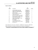
7.2 RECOMMENDED SPARE PARTS LIST
DESCRIPTION
KIT NUMBER
QUANTITY
replacement element kit for fluid filter 250026--982
250028--032
1
replacement element kit for air/fluid separator 250025--264
250028--033
1
replacement element kit for air filter 250025--421
250028--034
1
repair kit for motor shaft seal 250039--218
250028--035
1
repair kit, shaft seal installation
250034--267
1
repair kit for thermostat actuator 250025--413
250028--036
1
replacement kit for coil 250028--809
250028--387
1
repair kit for solenoid valve 250030--164
250038--849
1
replacement coil for solenoid valve 250030--164
250035--292
1
repair kit for minimum pressure/check valve 606058
250030--226
1
replacement piston seal kit for air inlet control valve
02250045--287
1
replacement piston for inlet control valve
02250044--811
1
replacement washer for inlet control valve
02250045--287
1
fluid, Sullube 32 (one gallon)
250009--396
1
fluid, Sullube 32 (five gallons)
250022--669
1
repair kit for ES--6 1/2” npt service connection 250026--066
250030--103
1
PLEASE NOTE: WHEN ORDERING PARTS, INDICATE SERIAL NUMBER OF COMPRESSOR
Summary of Contents for ES-6 series
Page 6: ...NOTES...
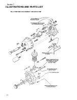
Page 30: ...Section 7 ILLUSTRATIONS AND PARTS LIST 24 ES 6 COMPRESSOR ASSEMBLY EXPLODED VIEW 5 5 AND 7 5KW...
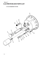
Page 32: ...Section 7 ILLUSTRATIONS AND PARTS LIST 26 7 3 FLUID MANAGEMENT SYSTEM...
Page 34: ...Section 7 ILLUSTRATIONS AND PARTS LIST 28 7 4 INLET FILTER...
Page 36: ...Section 7 ILLUSTRATIONS AND PARTS LIST 30 7 5 SEAL AND DRIVE GEAR...
Page 38: ...Section 7 ILLUSTRATIONS AND PARTS LIST 32 7 6 MOTOR HOUSING AND PARTS 7 5 10HP 5 5 7 5KW ONLY...
Page 42: ...Section 7 ILLUSTRATIONS AND PARTS LIST 36 7 8 COMPRESSOR SYSTEM...
Page 44: ...Section 7 ILLUSTRATIONS AND PARTS LIST 38 7 9 INLET CONTROL...
Page 46: ...Section 7 ILLUSTRATIONS AND PARTS LIST 40 7 10 CONTROL BOX...
Page 48: ...Section 7 ILLUSTRATIONS AND PARTS LIST 42 7 10 CONTROL BOX...
Page 52: ...Section 7 ILLUSTRATIONS AND PARTS LIST 46 7 12 FRAME CANOPY AND PARTS...
Page 56: ...Section 7 ILLUSTRATIONS AND PARTS LIST 50 7 14 WYE DELTA ELECTRIC BOX ES 6...
Page 58: ...Section 7 ILLUSTRATIONS AND PARTS LIST 52 7 15 DECAL GROUP 7 8 9 11 12...
Page 60: ...Section 7 ILLUSTRATIONS AND PARTS LIST 54 7 15 DECAL GROUP 13...
Page 62: ...Section 7 ILLUSTRATIONS AND PARTS LIST 56 7 16 WIRING DIAGRAM SINGLE PHASE 60Hz...
Page 63: ...Section 7 ILLUSTRATIONS AND PARTS LIST 57 7 17 WIRING DIAGRAM THREE PHASE 60Hz...
Page 64: ...Section 7 ILLUSTRATIONS AND PARTS LIST 58 7 18 WIRING DIAGRAM 50 Hz...
Page 65: ...Section 7 ILLUSTRATIONS AND PARTS LIST 59 7 19 WIRING DIAGRAM 50 Hz WYE DELTA...
Page 66: ...NOTES...
Page 67: ...NOTES...

