Section 7
ILLUSTRATIONS AND PARTS LIST
27
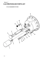
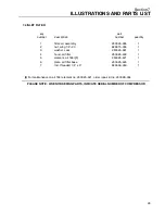
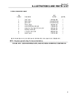
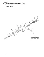
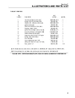
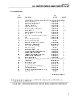
7.3 FLUID MANAGEMENT SYSTEM
key
part
number
description
number
quantity
1
element, fluid filter
(I)
250026--982
1
2
adapter, fluid filter
250025--914
1
3
cap, separator element
250026--038
1
4
o--ring, 2 3/16” x 3/32”
826502--139
1
5
element, separator air/fluid
(II)
250025--264
1
6
o--ring, 1 7/16” x 1/16”
826502--127
1
7
plug, hex head 1 1/16”--12 SAE
250039--359
1
8
glass, sight
250025--420
1
9
housing, bell
250025--309
1
10
capscrew, ferry head 1/2”--13 x 3”
828408--300
12
S
screw, socket ISO4762 m12 x 20 (metric)
829312--080
12
11
actuator, thermostat
(III)
250025--413
1
12
piston, thermostat
250025--415
1
13
spring, compression
250025--464
1
14
pin, roll 1/4” x 1 1/2”
827404--150
1
15
guide, thermostat spring
250025--417
1
16
o--ring
(IV)
250025--419
3
17
plug, thermostat 1 1/16”--12
250025--418
1
18
decal, fluid
(V)
--
1
(I)
For maintenance on fluid filter element no. 250026--982, order repair kit no. 250028--032.
(II)
For maintenance on air/fluid separator element no. 250025--264, order repair kit no. 250028--033.
(III)
For maintenance on thermostat actuator no. 250025--413, order repair kit no. 250028--036.
(IV)
For replacement only.
(V)
Decal will vary with compressor fluid fill requirement. Factory fill (Sullube 32) decal part no. is
02250069--389.
PLEASE NOTE: WHEN ORDERING PARTS, INDICATE SERIAL NUMBER OF COMPRESSOR
Summary of Contents for ES-6 series
Page 6: ...NOTES...
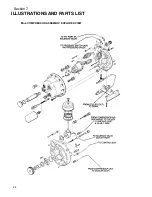
Page 30: ...Section 7 ILLUSTRATIONS AND PARTS LIST 24 ES 6 COMPRESSOR ASSEMBLY EXPLODED VIEW 5 5 AND 7 5KW...
Page 32: ...Section 7 ILLUSTRATIONS AND PARTS LIST 26 7 3 FLUID MANAGEMENT SYSTEM...
Page 34: ...Section 7 ILLUSTRATIONS AND PARTS LIST 28 7 4 INLET FILTER...
Page 36: ...Section 7 ILLUSTRATIONS AND PARTS LIST 30 7 5 SEAL AND DRIVE GEAR...
Page 38: ...Section 7 ILLUSTRATIONS AND PARTS LIST 32 7 6 MOTOR HOUSING AND PARTS 7 5 10HP 5 5 7 5KW ONLY...
Page 42: ...Section 7 ILLUSTRATIONS AND PARTS LIST 36 7 8 COMPRESSOR SYSTEM...
Page 44: ...Section 7 ILLUSTRATIONS AND PARTS LIST 38 7 9 INLET CONTROL...
Page 46: ...Section 7 ILLUSTRATIONS AND PARTS LIST 40 7 10 CONTROL BOX...
Page 48: ...Section 7 ILLUSTRATIONS AND PARTS LIST 42 7 10 CONTROL BOX...
Page 52: ...Section 7 ILLUSTRATIONS AND PARTS LIST 46 7 12 FRAME CANOPY AND PARTS...
Page 56: ...Section 7 ILLUSTRATIONS AND PARTS LIST 50 7 14 WYE DELTA ELECTRIC BOX ES 6...
Page 58: ...Section 7 ILLUSTRATIONS AND PARTS LIST 52 7 15 DECAL GROUP 7 8 9 11 12...
Page 60: ...Section 7 ILLUSTRATIONS AND PARTS LIST 54 7 15 DECAL GROUP 13...
Page 62: ...Section 7 ILLUSTRATIONS AND PARTS LIST 56 7 16 WIRING DIAGRAM SINGLE PHASE 60Hz...
Page 63: ...Section 7 ILLUSTRATIONS AND PARTS LIST 57 7 17 WIRING DIAGRAM THREE PHASE 60Hz...
Page 64: ...Section 7 ILLUSTRATIONS AND PARTS LIST 58 7 18 WIRING DIAGRAM 50 Hz...
Page 65: ...Section 7 ILLUSTRATIONS AND PARTS LIST 59 7 19 WIRING DIAGRAM 50 Hz WYE DELTA...
Page 66: ...NOTES...
Page 67: ...NOTES...

